Movable grouting pump with stirring function

A grouting pump, mobile technology, applied in cement mixing device, variable displacement pump parts, parts of pumping device for elastic fluid, etc. The grouting pump is troublesome to move and other problems, so as to avoid unstable working conditions, avoid manpower and material resources, and achieve good shock absorption and buffering effects.

Inactive Publication Date: 2021-08-10
XUZHOU BOAN TECH DEV +1
View PDF0 Cites 1 Cited by
  • Summary
  • Abstract
  • Description
  • Claims
  • Application Information

AI Technical Summary

Problems solved by technology

[0003] The purpose of the present invention is to provide a mobile grouting pump with stirring function to solve the problem that the existing grouting pump proposed in the background technology has poor shock absorption and buffering effect, which leads to insufficient stability of the working state of the grouting pump, and The existing grouting pump is troublesome to move, and it is easy to waste a lot of manpower and material resources, and the existing grouting pump has a poor mixing effect, and the cement or mortar is affected by the weather, thereby affecting the grouting effect, and the existing grouting pump The problem of inconvenient slurry pump feeding

Method used


Image

  • Movable grouting pump with stirring function
  • Movable grouting pump with stirring function
  • Movable grouting pump with stirring function

Examples


Embodiment Construction

[0026] The following will clearly and completely describe the technical solutions in the embodiments of the present invention with reference to the accompanying drawings in the embodiments of the present invention. Obviously, the described embodiments are only some, not all, embodiments of the present invention. Based on the embodiments of the present invention, all other embodiments obtained by persons of ordinary skill in the art without making creative efforts belong to the protection scope of the present invention.

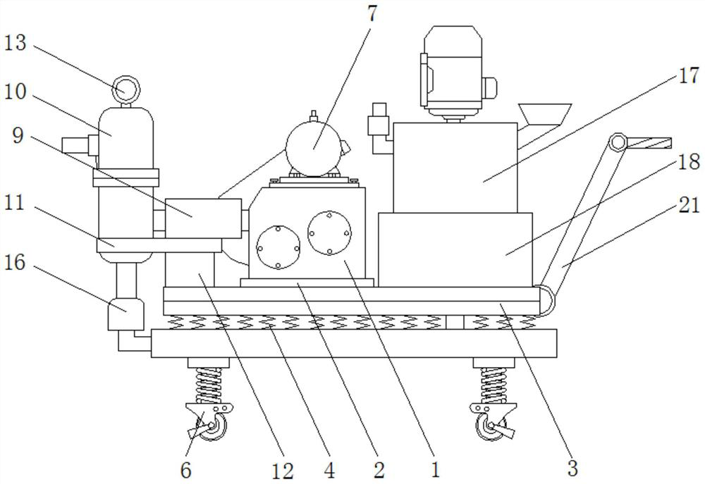
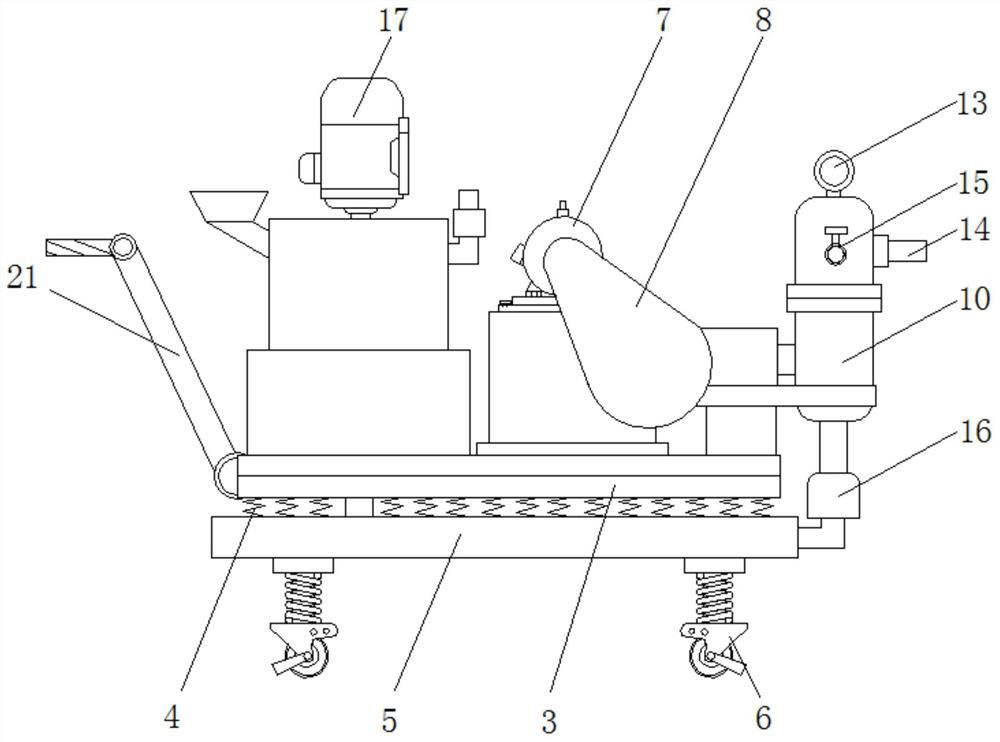
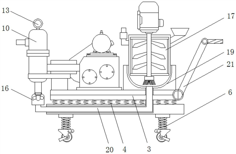
[0027] see Figure 1-7 , the present invention provides a mobile grouting pump with stirring function, such as figure 1 , figure 2 , Figure 4 and Figure 5As shown, the grouting pump body 1 is fixedly connected to the shock absorbing plate 3 through the fixing plate 2, and a plurality of first shock absorbing springs 4 are arranged under the bottom of the shock absorbing plate 3, and the shock absorbing plate 3 is connected to the shock absorbing plate 3 ...


PUM


Abstract

The invention discloses a movable grouting pump with the stirring function. The movable grouting pump comprises a grouting pump body, a pure copper motor, a grouting cylinder, a fixing block, a pressure gauge, a stirring mechanism, a containing groove, a discharging pipe and an adjusting mechanism, wherein the grouting pump body is fixedly connected with a damping plate through a fixing plate, and the damping plate is fixedly connected with a bottom plate through a first damping spring; the pure copper motor is arranged above the grouting pump body; one side of the grouting cylinder is fixedly connected with the grouting pump body through a piston material cylinder; the fixing block is arranged above one side of the damping plate; the pressure gauge is arranged at the top end of the grouting cylinder; a pressure relief valve is arranged on the other side of the grouting cylinder; the stirring mechanism is arranged on one side of the grouting pump body; and the containing groove is formed in a containing platform. According to the movable grouting pump with the stirring function, a moving mechanism and a stirring mechanism are arranged, the moving mechanism conveniently drives the grouting pump body to move through rolling wheels, the stirring mechanism conveniently and evenly stirs cement mortar, and grouting of the grouting pump is facilitated.

Description

technical field [0001] The invention relates to the technical field of grouting pumps, in particular to a mobile grouting pump with stirring function. Background technique [0002] Grouting pump is the key equipment in grouting construction. It is widely used in mines, tunnels, water conservancy, subways, buildings, bridges, mines and other construction sites for grouting water blocking, filling gaps, and strengthening broken rock formations. more extensive. At present, most of the grouting pumps used in mines or large-scale construction sites are pressure injection cement or mortar, which are composed of independent mixers and grouting pumps. The equipment is huge and covers a large area. The cement or mortar is placed between the mixer and the grouting pump In the process of inter-transportation, it is greatly affected by the weather, and it will also cause the loss of water, which will cause the cement or mortar to condense and affect the grouting effect. When the grout...

Claims


Application Information

Patent Timeline
Patent Type & Authority Applications(China)
IPC IPC(8): B28C5/16B28C5/08F04B15/02F04B53/00E21D11/10E04G21/02F16F15/067
CPCB28C5/0806B28C5/0856B28C5/16E04G21/02E21D11/105F04B15/02F04B53/00F16F15/067
Inventor 谭家贵张连军李克相张海宾张茂元郭建忠孙京赵东方
Owner XUZHOU BOAN TECH DEV
Why Eureka
Try Eureka