Automatic pipe cutting equipment and pipe cutting method
A technology for automatic cutting and cutting of pipes, which is applied to shearing machines, metal processing equipment, pipe cutting devices, etc. It can solve the problems of complex pipe cutting length control, complex structure of pipe cutting machines, and high equipment costs, so as to ensure the feeding efficiency , Increase personnel safety and improve efficiency
- Summary
- Abstract
- Description
- Claims
- Application Information
AI Technical Summary
Problems solved by technology
Method used
Image

Examples
Embodiment 1
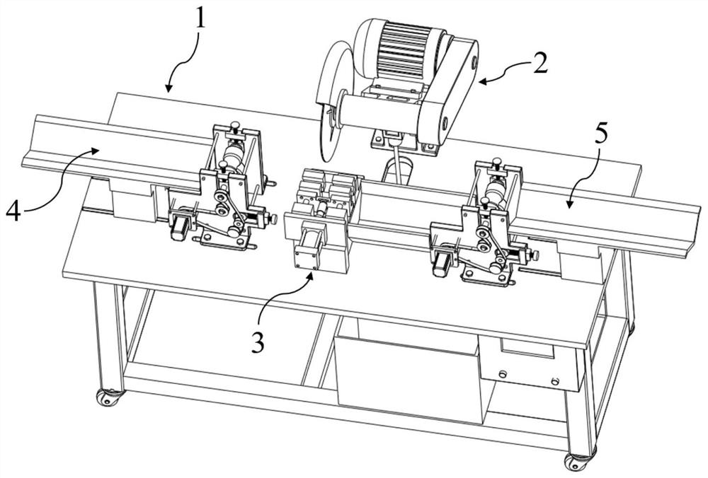
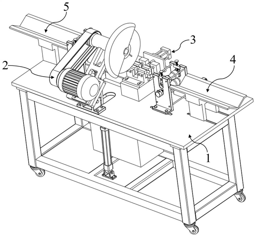
[0083] The pipe material automatic cutting equipment of the present embodiment comprises:
[0084] Workbench 1;
[0085] Cutting unit 2, which is located in the middle of the workbench 1, and executes the pipe cutting action;
[0086] A fixture 3, which is arranged on the top surface of the middle part of the workbench 1, the fixture 3 is located in front of the cutting unit 2, and holds the pipe to be cut;
[0087] The feeding unit 4 is arranged on the top surface of the workbench 1 on one side of the clamp 3, and the feeding unit 4 transports the pipe to be cut along the direction towards the clamp 3;
[0088] The feeding unit 5 is arranged on the top surface of the workbench 1 on the other side of the clamp 3 , and the feeding unit 5 transports the cut pipe along the direction away from the clamp 3 .
[0089] The existing cutting equipment mainly has the following disadvantages. On the one hand, the degree of automation is low, and the loading, cutting, feeding, and measu...
Embodiment 2
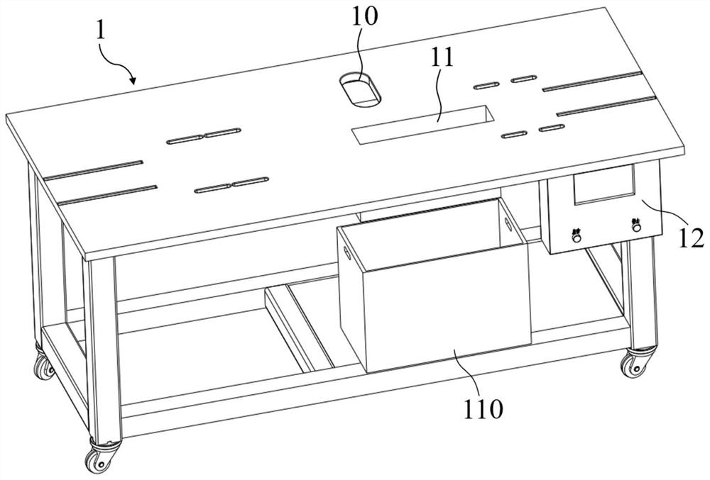
[0093] The pipe automatic cutting equipment of this embodiment is further improved on the basis of Embodiment 1, and the top surface of the middle part of the workbench 1 is provided with a relief hole 10;
[0094] The cutting unit 2 includes:
[0095] A hinged seat 20, which is fixedly connected to the edge of the top surface of the middle part of the workbench 1, and the relief hole 10 is located in front of the hinged seat 120;
[0096] Cutting machine 21, the bottom of one end is hinged with the hinge seat 20, and the other end is the blade end 210 arranged towards the front of the workbench 1;
[0097] Cylinder one 22, its bottom is hinged on the workbench 1 bottom just below the relief hole 10 by hinge seat two 23, and cylinder one 22 top telescopic rod stretches out from the relief hole 10 and is hinged with cutting machine 21 middle part bottom surface.
[0098] Such as image 3 with Figure 4 As shown, the cutting action of the cutting unit 2 in this embodiment is ...
Embodiment 3
[0102] The pipe automatic cutting equipment of this embodiment is further improved on the basis of Embodiment 2, and the clamp 3 includes:
[0103] Base 30, which is fixedly connected to the top surface of the middle part of workbench 1;
[0104] fixed jaw 31, which is fixed on the rear end of the top surface of the base 30;
[0105] The movable jaw 32 is movable in front of the fixed jaw 31, and the movable jaw 32 and the fixed jaw 31 have the same shape and are symmetrically arranged;
[0106] End plate 33, which is vertically fixed on the top surface of workbench 1 in front of base 30;
[0107] The second cylinder 34 is fixed on the front end of the end plate 33, and the telescopic end of the second cylinder 34 passes through the end plate 33 and is connected to the front end of the movable jaw 32 in transmission.
[0108] Such as figure 1 with Figure 5 As shown, the jig 3 is arranged at the position where the blade of the cutting unit 2 is located when the cutter 21 i...
PUM
 Abstract
Description
Claims
Application Information
 - R&D Engineer
- R&D Manager
- IP Professional
- Industry Leading Data Capabilities
- Powerful AI technology
- Patent DNA Extraction
Browse by: Latest US Patents, China's latest patents, Technical Efficacy Thesaurus, Application Domain, Technology Topic.
© 2024 PatSnap. All rights reserved.Legal|Privacy policy|Modern Slavery Act Transparency Statement|Sitemap