
Handheld constructional engineering stirring device

A technology for construction engineering and mixing devices, which is applied in cement mixing devices, electromechanical devices, measuring devices, etc., can solve the problems of single function, reduced reliability, equipment volume and increased design cost, and achieves good mixing effect and improves mixing effect. Effect

Pending Publication Date: 2021-08-13
翟文娜
View PDF9 Cites 0 Cited by
  • Summary
  • Abstract
  • Description
  • Claims
  • Application Information

AI Technical Summary

Problems solved by technology

But this device also has the disadvantage that when the device is used, the base needs to be placed inside the container. When the inside of the container is uneven, the device is inconvenient to use. At the same time, when the device is used, it is driven by manpower. When relatively viscous, manpower is difficult to rotate, time-consuming and laborious. Simultaneously, the structure of the device is simple and the function is single, and the single stirring method makes the stirring effect poor. Other existing mechanisms that can realize multiple stirring modes, such as CN2644507Y / CN112191129A realize Forward and reverse stirring / up and down tumbling stirring / vibration stirring and the above-mentioned mixed motion mode stirring, but need to use multiple driving mechanisms such as forward and reverse motors / hydraulic cylinders or lead screw drive mechanisms / electromagnetic vibrators at the same time, which will make The complexity of the entire control logic reduces the reliability and increases the volume and design cost of the entire equipment. In view of this, we propose a hand-held construction engineering mixing device

Method used


Image

  • Handheld constructional engineering stirring device
  • Handheld constructional engineering stirring device
  • Handheld constructional engineering stirring device

Examples


Embodiment Construction

[0025] In describing the present invention, it should be understood that the terms "center", "longitudinal", "transverse", "length", "width", "thickness", "upper", "lower", "front", " Orientation indicated by rear, left, right, vertical, horizontal, top, bottom, inside, outside, clockwise, counterclockwise, etc. The positional relationship is based on the orientation or positional relationship shown in the drawings, and is only for the convenience of describing the present invention and simplifying the description, rather than indicating or implying that the referred device or element must have a specific orientation, be constructed and operated in a specific orientation, Therefore, it should not be construed as limiting the invention.

[0026] In the description of the present invention, "plurality" means two or more, unless otherwise specifically defined.

[0027] In the description of the present invention, it should be noted that, unless otherwise specified and limited, t...


PUM


Abstract

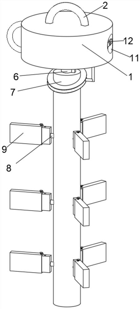
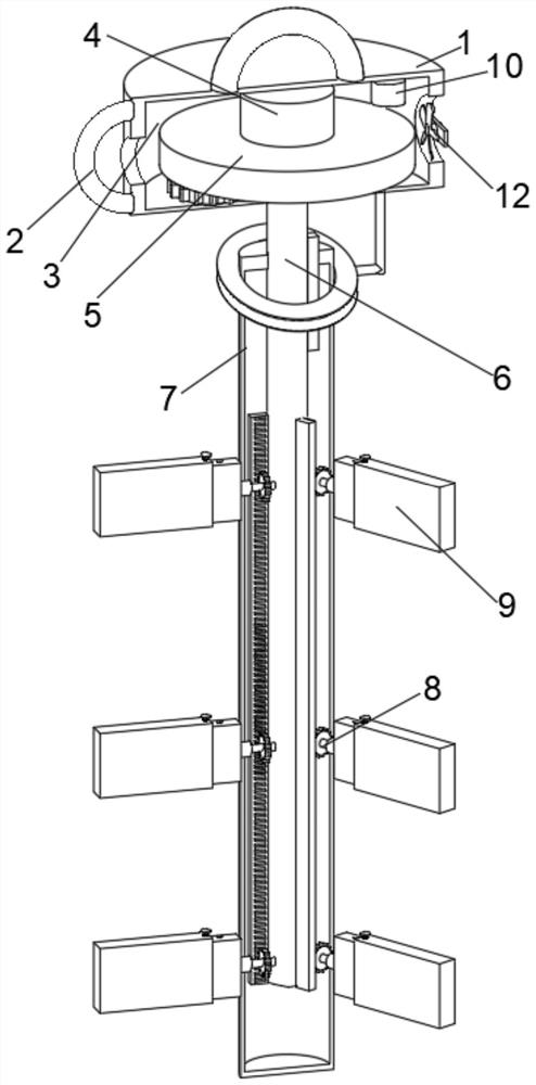
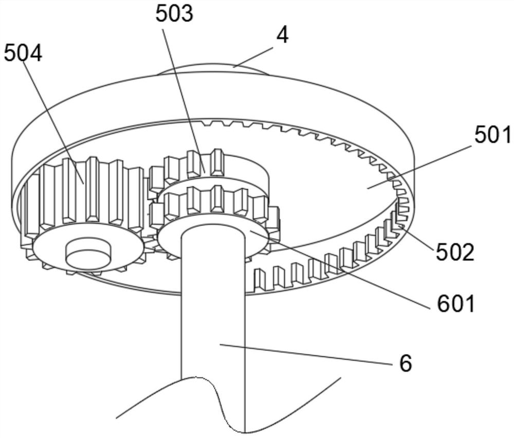
The invention discloses a handheld constructional engineering stirring device, and belongs to the technical field of constructional engineering. The handheld constructional engineering stirring device comprises a top plate, wherein handles are welded to the top face and the side wall of the top plate, and a placement groove is formed inside the top plate; the outer wall of the lower end of a rotating shaft is sleeved with an adjusting pipe, a plurality of vibration assemblies are arranged on the outer wall of the lower end of the adjusting pipe in an annular structure, and stirring blades are arranged on the outer sides of the vibration assemblies; and a temperature sensor is arranged on the inner wall of the placement groove, a heat dissipation opening is formed in the outer wall of the top plate, and a heat dissipation fan is arranged on the inner wall of the heat dissipation opening. By arranging a direction changing assembly, when stirring is needed, a motor is used for driving a rotating disc to rotate, the rotating disc can drive a connected incomplete gear to rotate, and then a transmission gear is driven to rotate reversely, so that the stirring blades on the adjusting pipe rotate reversely; and materials are stirred, and the rotating direction is continuously changed, so that the stirring effect is better, and the problem of non-uniform stirring caused by rotation in the same direction is avoided.

Description

technical field [0001] The invention relates to the technical field of construction engineering, and more specifically relates to a hand-held stirring device for construction engineering. Background technique [0002] On the construction site, it is often necessary to stir the construction materials such as concrete cement, putty powder and paint in the barrel container evenly. Now a hand-held mixer has been developed, which uses a machine instead of labor, saving time and effort than before, but this tool still needs to be manually moved up, down, left, and right to ensure that the putty in the container is evenly stirred. The prior art CN112535983A discloses a hand-held The large-scale construction engineering mixing device manually drives the mixing blade to rotate and mix by pressing and pulling. It is suitable for mixing a small amount of building materials in the container. The operation is labor-saving, the work efficiency is high, and the labor burden of workers is r...

Claims


Application Information

Patent Timeline
Patent Type & Authority Applications(China)
IPC IPC(8): B28C5/08B28C5/48G01K1/14H02K7/14H02K9/04
CPCB28C5/08B28C5/485B28C5/0831B28C5/0806G01K1/14H02K9/04H02K7/14
Inventor 肖义涛
Owner 翟文娜
Learn More