Eureka AIR delivers breakthrough ideas for toughest innovation challenges, trusted by R&D personnel around the world.

A fully precast concrete floor connection structure and design calculation method

A technology of prefabricated concrete and concrete, which is applied in the direction of floor slab, building structure, design optimization/simulation, etc. Decoration and decoration damage and other problems, to achieve the effect of improving collaborative deformation ability, simple and fast construction, and saving construction period

Active Publication Date: 2021-10-08
CENT RES INST OF BUILDING & CONSTR CO LTD MCC GRP +1
View PDF6 Cites 0 Cited by
  • Summary
  • Abstract
  • Description
  • Claims
  • Application Information

AI Technical Summary

Problems solved by technology

However, limited by the size of the floor slabs during transportation, there are inevitably joints between adjacent prefabricated floor slabs
The physical connection joints between fully precast floors affect the in-plane shear resistance, bending stiffness and bearing capacity of the floors, resulting in a significant decrease in the integrity of the floors; in addition, under the action of vertical loads, the deformation of the fully precast panels on both sides of the joints is uncoordinated, etc. problems, leading to damage to the decoration at the joints, affecting the comfort and aesthetics of use

Method used


Image

  • A fully precast concrete floor connection structure and design calculation method
  • A fully precast concrete floor connection structure and design calculation method
  • A fully precast concrete floor connection structure and design calculation method

Examples


Embodiment Construction

[0072] For purposes of embodiments of the present invention, technical solutions and advantages clearer, the following Examples and the accompanying drawings, described in further detail embodiments of the present invention. Here, a schematic embodiment of the present invention and a description thereof are for explaining the invention, but is not limited to the present invention.

[0073] In the description of the present invention, it is to be understood that the term "comprises / comprising", "consisting of ......" or any other variation thereof are intended to cover a non-exclusive inclusion, such that the product comprises a series of elements, devices, process or method include not only those elements, but also can have other elements not explicitly listed, or further includes elements for such products, equipment, processes or methods inherent. In the absence of more restrictions, the factors "include / include ...", "consisting of ...", are not excluded in addition to the ...


PUM


Abstract

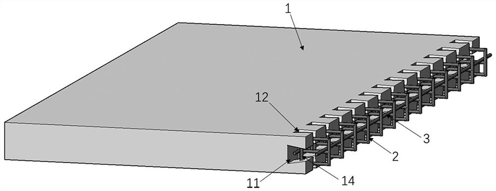
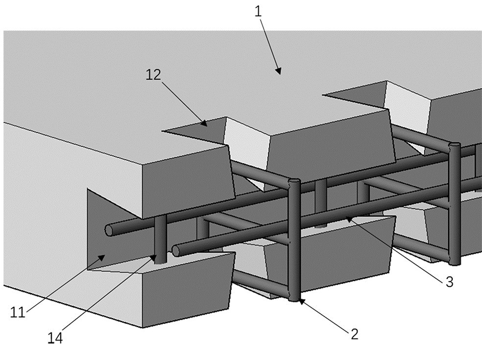
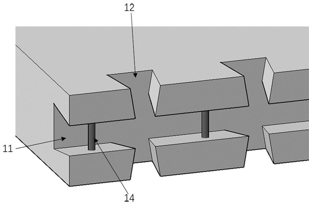
The invention discloses a fully prefabricated concrete floor connection structure and a design calculation method. The connection structure includes prefabricated concrete floors (1) on both sides, a rear reinforcement frame (2), a rear through longitudinal reinforcement (3) and a post-casting Concrete (4), the prefabricated concrete floor (1) is provided with longitudinal through grooves (11) and multiple vertical through grooves (12) on the side of the connecting side; into the through groove (12); the rear through longitudinal reinforcement (3) is installed in the rear reinforcement frame (2); the post-cast concrete (4) is poured in the longitudinal through groove (11) and multiple vertical through grooves ( 12) in. The invention can significantly improve the in-plane shear resistance, flexural rigidity and bearing capacity of the fully prefabricated floor slab, and ensure the coordination of deformation at the joints of the slab when bearing vertical loads, and can achieve the service performance similar to that of the integral cast-in-place floor. The invention has reliable performance, simple structure, quick construction and environmental protection.

Description

Technical field [0001] The present invention relates to the field of building structural connection structure, in particular, to a full prefabricated concrete floor connection structure and design calculation method. Background technique [0002] As an important part of the overall building structure, the floor is not only assumed vertical load, but also transmits the horizontal load generated by the seismic role and wind load to the anti-side system. Traditional steel-cast-in-place concrete floor exhibits excellent mechanical properties, but there is still a large number of workers in the construction process to conduct on-site template production, steel binding and concrete pouring, etc. There are problems such as cumbersome, high workload, low construction efficiency; In addition, with the shortage of labor, the labor costs are greatly increased; the large-scale live wet operation has caused environmental pollution, which does not meet the development direction of building ind...

Claims


Application Information

Patent Timeline
Patent Type & Authority Patents(China)
IPC IPC(8): E04B5/02E04B5/04E04B1/682G06F30/13G06F30/20
CPCE04B1/6801E04B5/023E04B5/04G06F30/13G06F30/20G06F2119/14
Inventor 刘晓刚郑明召王皓岳清瑞孙鸿敏刘洁
Owner CENT RES INST OF BUILDING & CONSTR CO LTD MCC GRP
Why Eureka
Eureka Blog
Learn More