
Hypersonic air inlet layout for annular combustion chamber

An annular combustor and hypersonic technology, applied in the air inlet of turbine/propulsion device, combustion air/combustion-air treatment, high-efficiency propulsion technology, etc., can solve the problem of engine failure to organize combustion normally, reduce engine performance, thermal protection Improve the difficulty and other issues to achieve the effect of effective full-bomb frontal area, reduce viscous loss, and reduce the difficulty of thermal protection

Active Publication Date: 2021-08-13
NAT UNIV OF DEFENSE TECH
View PDF4 Cites 4 Cited by
  • Summary
  • Abstract
  • Description
  • Claims
  • Application Information

AI Technical Summary

Problems solved by technology

[0008] Head air intake solution: The length of the engine internal flow channel of the head air intake solution is coupled with the length of the aircraft. The length of the engine internal flow channel needs to match the length of the aircraft, resulting in an excessively long internal flow channel and a large flow loss, thereby reducing engine performance or causing The engine cannot properly organize combustion;
[0009] Four-module X-type air intake scheme (two-dimensional air intake): This scheme can place the air intake on the body or tail of the aircraft, but because the boundary layer is thick, it must be designed with a partition that strips the boundary layer, resulting in structural weight Increased, increasing the difficulty of thermal protection

Method used

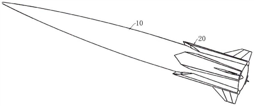
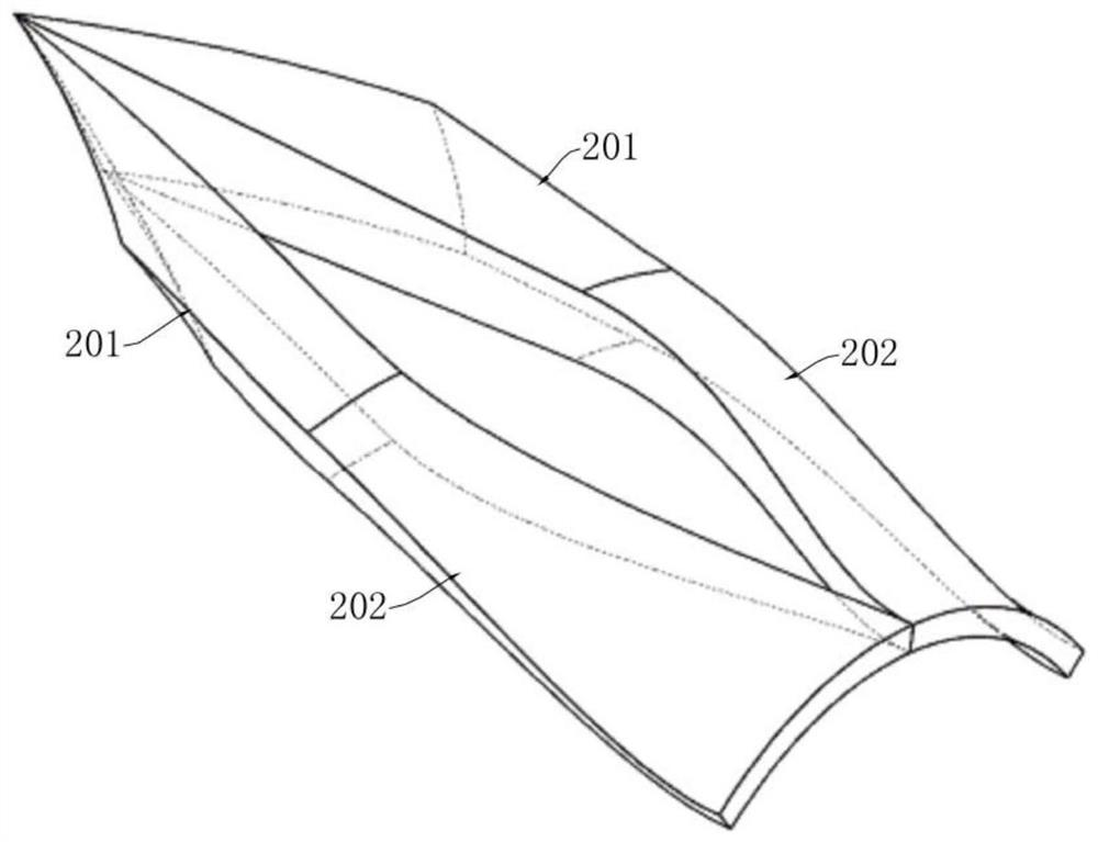

Image

  • Hypersonic air inlet layout for annular combustion chamber
  • Hypersonic air inlet layout for annular combustion chamber
  • Hypersonic air inlet layout for annular combustion chamber

Examples


Embodiment Construction

[0043] The technical solutions in the embodiments of the present invention will be clearly and completely described below with reference to the accompanying drawings in the embodiments of the present invention. Obviously, the described embodiments are only a part of the embodiments of the present invention, not all of the embodiments. Based on the embodiments of the present invention, all other embodiments obtained by those of ordinary skill in the art without creative efforts shall fall within the protection scope of the present invention.

[0044] It should be noted that all directional indications (such as up, down, left, right, front, back...) in the embodiments of the present invention are only used to explain the relationship between various components under a certain posture (as shown in the accompanying drawings). The relative positional relationship, the movement situation, etc., if the specific posture changes, the directional indication also changes accordingly.

[...


PUM


Abstract

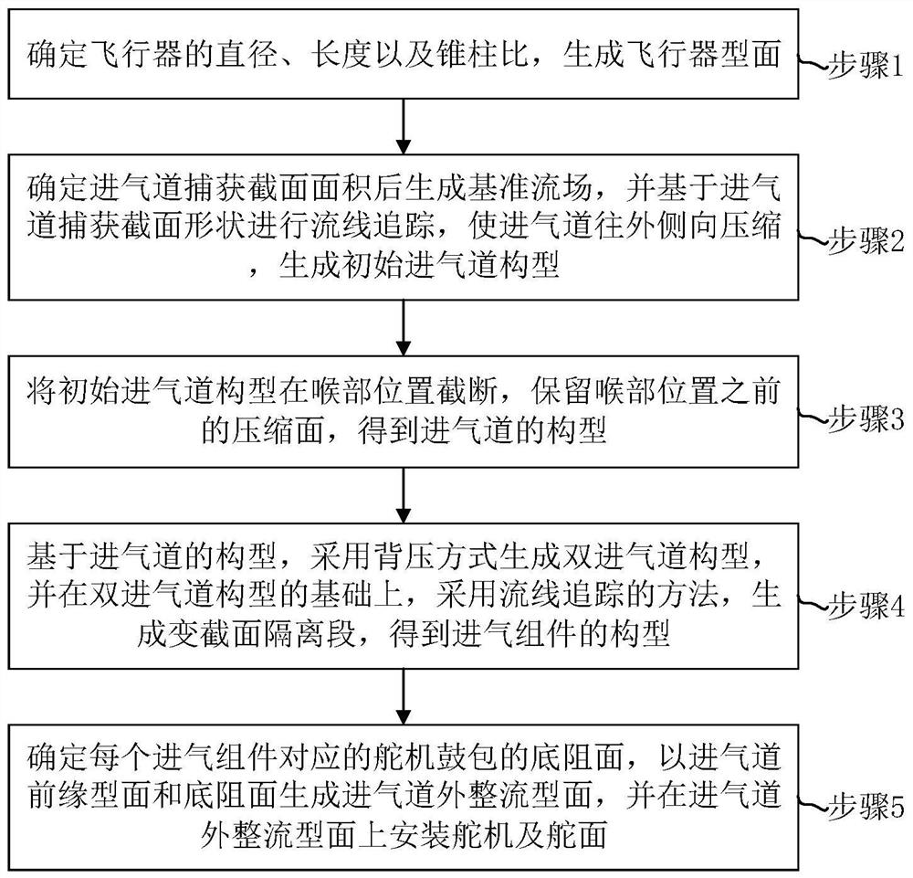
The invention discloses a hypersonic air inlet layout for an annular combustion chamber. The hypersonic air inlet layout comprises the steps that the diameter, the length and the cone-to-column ratio of an aircraft are determined, and an aircraft profile is generated; a reference flow field is generated after the capture sectional area of an air inlet channel is determined, and streamline tracking is performed to generate an initial air inlet channel configuration; the initial air inlet channel configuration is cut off at the throat position, and an air inlet channel configuration is obtained; a double-air-inlet-channel configuration is generated based on the air inlet channel configuration, and a variable-section isolation section is generated by adopting a streamline tracking method to obtain the configuration of air inlet assemblies; and a bottom resistance surface of a steering engine bulge corresponding to each air inlet assembly is determined, an air inlet channel outer rectification profile is generated by using the air inlet channel front edge profile and the bottom resistance surface, and a steering engine and a control surface are installed on the inlet channel outer rectification profile. The lengths of the air inlet channel and the isolation section can be greatly reduced, so that the viscosity loss of flowing of an inner flow channel is reduced, the boundary layer is swept through shock waves, and the air inlet channel and the isolation section are uniform in flow field, high in flow field quality and high in back pressure resistance.

Description

technical field [0001] The invention relates to the technical field of intake port design, in particular to a hypersonic intake layout for an annular combustion chamber. Background technique [0002] Air-breathing hypersonic vehicle has huge military and civil potential because of its fast speed, long range and strong maneuverability. [0003] The air-breathing hypersonic vehicle faces the challenge of matching thrust and drag due to its fast flight speed and large flight resistance. Therefore, it is necessary to carry out the integrated design of the air inlet and the fuselage. The existing air-breathing hypersonic vehicle fuselage and air inlet integrated design are mainly divided into axisymmetric layout, lift body layout and waverider layout, which mainly use axisymmetric compression, two-dimensional compression intake and three-dimensional internal compression respectively. Switch to compressed intake form. [0004] The annular combustion chamber is mainly used in air...

Claims


Application Information

Patent Timeline
IPC IPC(8): F02C7/04
CPCF02C7/04Y02T50/60
Inventor 赵一龙赵玉新王振国何刚王前程
Owner NAT UNIV OF DEFENSE TECH
Learn More