
Flatness optimization method for sum-difference beam signal level of phased-array antenna

A phased array antenna and optimization method technology, which is applied to the antenna radiation pattern and other directions, can solve the problems of interfering with the self-tracking function of the phased array antenna, the fluctuation of the sum and difference beam signal levels, and the inability to adjust the excitation amplitude. The effect of reducing the side lobe level, improving the anti-interference ability, and accelerating the convergence speed

Active Publication Date: 2021-08-13
10TH RES INST OF CETC
View PDF13 Cites 2 Cited by
  • Summary
  • Abstract
  • Description
  • Claims
  • Application Information

AI Technical Summary

Problems solved by technology

In this process, the phase can be adjusted, but the amplitude of the excitation cannot be adjusted. The addition or departure of the array elements or sub-arrays will cause fluctuations in the signal levels of the sum and difference beams.
However, the fluctuation of the signal level of the sum and difference beams will interfere with the self-tracking function of the phased array antenna to the space target, and in severe cases, the self-tracking target will be lost.

Method used


Image

  • Flatness optimization method for sum-difference beam signal level of phased-array antenna
  • Flatness optimization method for sum-difference beam signal level of phased-array antenna
  • Flatness optimization method for sum-difference beam signal level of phased-array antenna

Examples


Embodiment Construction

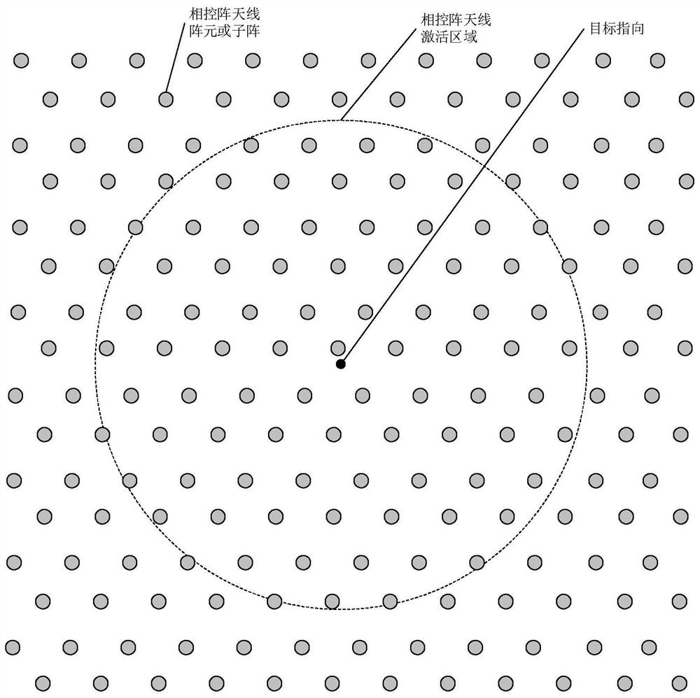
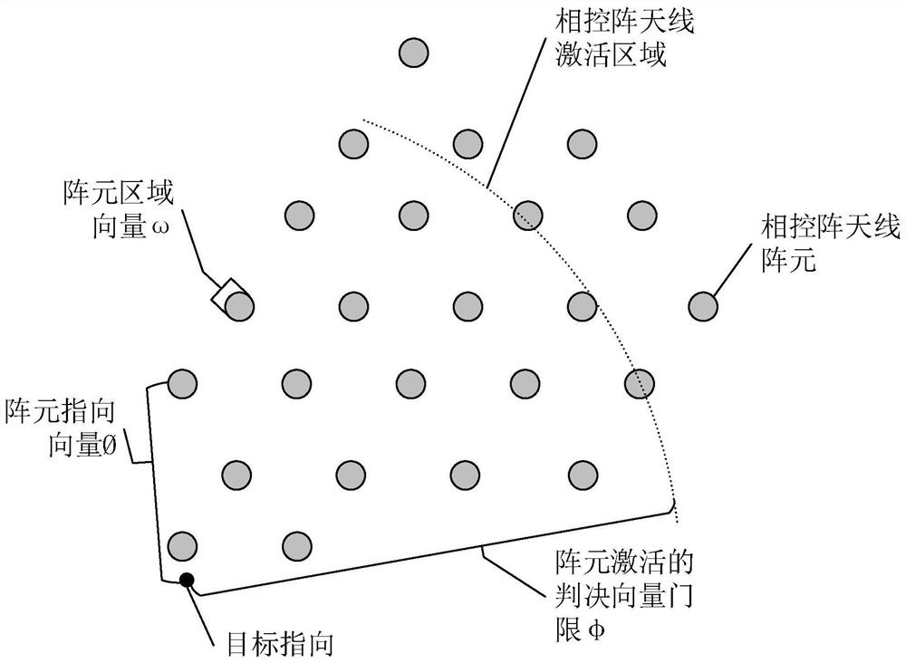
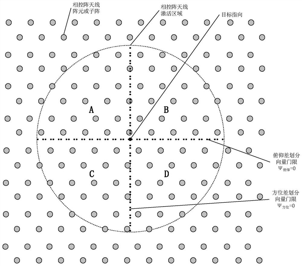
[0019] refer to figure 1 and figure 2, according to the present invention, utilize phased array antenna element or subarray, realize the peak side lobe level optimization of linear sparse array based on the optimization method of iterative Fast Fourier Transform (FFT) algorithm; Utilize phased array antenna to activate According to the Fourier transform pair relationship between the area excitation array factor and the array element excitation, the iterative cycle is performed on different initial random array element excitations to obtain the optimal array element distribution; according to the target orientation and the position of the array element or sub-array Information and a given array factor, the excitation coefficient of the array element is obtained by using a cyclic iteration method, and the coupling between the excitation source and the eigenmode CMA is analyzed according to the given weighting coefficient algorithm, and the mode weighting coefficient (MWC) is a...


PUM


Abstract

According to a flatness optimization method for the sum-difference beam signal level of a phased-array antenna provided by the invention, the consumed hardware resources are small, and the beam formation of the multi-beam phased-array antenna can be improved. The method is realized through the following technical scheme: realizing peak sidelobe level optimization of a linear sparse array based on an iterative FFT algorithm; respectively carrying out iterative circulation on different initial random array element excitations by utilizing a Fourier transform pair relation between an excitation array factor and array element excitations in an activation region of the phased-array antenna to obtain optimal array element distribution; obtaining an array element excitation coefficient in a loop iteration mode, calculating sum and difference beam weighting coefficients of each array element or sub-array, completing sum and difference beam level smooth sliding design of the phased-array antenna during self-tracking of a space target according to an automatically generated excitation signal, and based on the sum and difference beam level smooth sliding design, obtaining the corrected sum and difference beam levels by using the difference array division characteristic of the multi-beam forming spherical array antenna.

Description

technical field [0001] The invention relates to an optimization method of beam synthesis for improving the flatness of digital multi-beam phased array antenna and beam and differential beam signal levels. Background technique [0002] The one-dimensional scanning phased array antenna has the characteristics of narrow beam and low sidelobe in the azimuth plane, and realizes the sum and difference beam in the elevation plane. When the monopulse antenna beam is scanning in azimuth, its polarization characteristics are constantly changing. A multibeam antenna (multibeamantenna) is an antenna that can generate multiple sharp beams. These sharp beams (called meta-beams) can be combined into one or several shaped beams to cover specific airspace. There are three basic forms of multi-beam antennas: lens type, reflector type and phased array type. There are also hybrids using phased arrays as reflector or lens feeds. In array beamforming, the beam direction Figure 1 It is genera...

Claims


Application Information

Patent Timeline
IPC IPC(8): G01R29/10
CPCG01R29/10
Inventor 王文政杜丹扈景召陈煜航官劲
Owner 10TH RES INST OF CETC
Learn More