
Device and method for identifying and cutting natural gas hydrate layer section in casing pipe on site

A hydrate and natural gas technology, applied in the field of natural gas hydrate exploration, can solve the problems of affecting the occurrence state of hydrate, the accuracy of cutting horizons is not high, and the efficiency of hydrate samples is low, so as to improve sampling accuracy and reduce manpower Cost, effect of increasing acquisition rate

Active Publication Date: 2021-08-13
QINGDAO INST OF MARINE GEOLOGY
View PDF7 Cites 0 Cited by
  • Summary
  • Abstract
  • Description
  • Claims
  • Application Information

AI Technical Summary

Problems solved by technology

However, hydrates will decompose automatically when exposed to the air in field operations. The existing technology is inefficient in accurately identifying and cutting hydrate samples in the casing, resulting in a large loss of hydrate samples during the collection process, which affects follow-up work. Research and testing on the occurrence state of in-situ hydrate under the seabed
In addition, because there is no scale and other marks used to indicate the specific horizon in the casing, the accuracy of cutting the horizon is not high, which also causes the loss of hydrate samples
[0004] At present, there is no complete device and scheme to directly complete the above work. Therefore, it is urgent to design a device and method that can identify and cut the natural gas hydrate interval in the casing in an integrated manner.

Method used


Image

  • Device and method for identifying and cutting natural gas hydrate layer section in casing pipe on site
  • Device and method for identifying and cutting natural gas hydrate layer section in casing pipe on site

Examples


Embodiment Construction

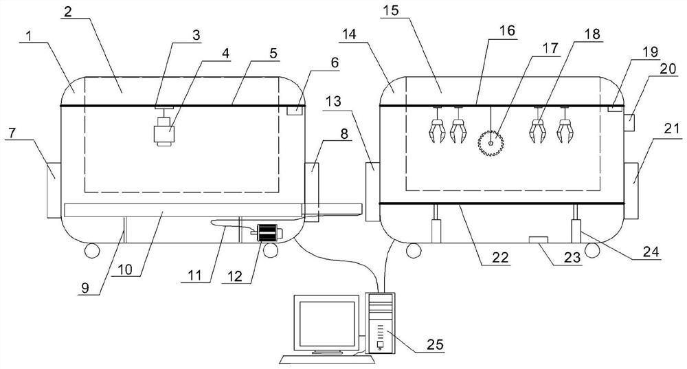
[0033] In order to make it easier for those skilled in the art to understand the present invention, the specific implementation manners of the present invention will be described below with reference to the accompanying drawings.

[0034] Such as figure 1 As shown, a device and method for identifying and cutting hydrates in a casing is completed by two units of temperature measurement and cutting, wherein the temperature measurement unit includes:

[0035] The temperature measurement housing 1 is used to assemble the internal parts of the temperature measurement unit.

[0036] The temperature measurement transparent cover 2 is hinged with the temperature measurement housing 1 and can be opened to facilitate observation of internal sample measurement conditions.

[0037] The temperature-measuring inlet 7 and the temperature-measuring outlet 8 are used for transferring the core casing into the temperature-measuring housing 1 and openings for taking out the equipment.

[0038] ...


PUM


Abstract

The invention relates to the technical field of natural gas hydrate exploration, in particular to a device and method for identifying and cutting a natural gas hydrate interval in a casing pipe on site. The device comprises a temperature measuring unit and a cutting unit horizontally arranged with the temperature measuring unit. And the temperature measuring unit comprises a temperature measuring shell, a temperature measuring transparent cover, a movable temperature measuring mechanism, a temperature measuring pipe inlet, a temperature measuring pipe outlet and a sleeve transfer mechanism. The cutting unit comprises a cutting shell, a cutting transparent cover, a movable sleeve clamping and cutting mechanism, a cutting pipe inlet, a cutting pipe outlet and a carrying platform. According to the invention, the identification-acquisition integrated operation of the hydrate-containing layer in the casing pipe can be realized, the acquisition rate of the hydrate sample is improved, and the loss of the hydrate in the process of acquiring the hydrate from the casing pipe is reduced. In addition, the sampling accuracy is also improved through the constraint of the actual measurement temperature difference. And powder generated in operation can be controlled in the equipment for centralized treatment, so that dust pollution on a construction site is avoided.

Description

technical field [0001] The invention relates to the technical field of natural gas hydrate exploration, in particular to a device and method for on-site identification and cutting of natural gas hydrate intervals in a casing. Background technique [0002] Natural gas hydrate (hereinafter referred to as "hydrate") is considered to be a potential green and clean energy in the 21st century, and its commercial exploration and development technology has always been an important direction for governments to explore and develop. An important engineering node in its industrial process is to obtain samples of hydrates in the rock formations under the seabed in deep sea environments. The successful acquisition of the samples is an affirmation of the understanding of hydrate occurrence laws in the previous stage and a verification of the accuracy of the collected data. The trial production of hydrates in the engineering stage provides strong support for physical testing and scheme desi...

Claims


Application Information

Patent Timeline
Patent Type & Authority Applications(China)
IPC IPC(8): G01V9/00
CPCG01V9/00G01V9/005
Inventor 李昂蔡峰李清闫桂京孙运宝董刚骆迪
Owner QINGDAO INST OF MARINE GEOLOGY
Learn More