Staggered fully-shielded wire, transformer based on staggered fully-shielded wire and staggered fully-shielded wire based on multi-phase current

A multi-phase current, fully shielded technology, applied in transformer/inductor components, transformer/inductor coils/windings/connections, preventing/reducing unwanted electrical/magnetic effects, etc., can solve high-frequency AC impedance The degree of improvement is limited, it is not suitable for mass production, and the structure of Litz wire is complex. It can solve the problems of high frequency and high energy transfer, reduce proximity effect and skin effect, and facilitate mass production.

Pending Publication Date: 2021-08-13
龙腾
View PDF3 Cites 0 Cited by
  • Summary
  • Abstract
  • Description
  • Claims
  • Application Information

AI Technical Summary

Problems solved by technology

However, the Litz wire is not only complicated in process and high in cost, but also due to the influence of the proximity effect, the current inside the conductor is still extremely uneven, and the improvement of high-frequency AC impedance is limited.
In addition, the structure of the litz wire is complex, and the winding is also very complicated, which is not suitable for mass production
Moreover, because each individual wire of the Litz wire needs to be insulated, the cross-sectional area of ​​the horizontal conductor is large, and the volume occupied is large.

Method used


Image

  • Staggered fully-shielded wire, transformer based on staggered fully-shielded wire and staggered fully-shielded wire based on multi-phase current
  • Staggered fully-shielded wire, transformer based on staggered fully-shielded wire and staggered fully-shielded wire based on multi-phase current
  • Staggered fully-shielded wire, transformer based on staggered fully-shielded wire and staggered fully-shielded wire based on multi-phase current

Examples


Embodiment Construction

[0061] Specific embodiments of the present invention will be described in detail below in conjunction with the accompanying drawings.

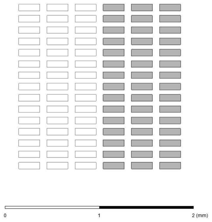
[0062] Embodiment 1 of staggered fully shielded wires such as Figure 4 As shown, it includes several wire layers superimposed up and down, each layer of wire layer is provided with a number of input wires and output wires, the input wires and output wires on each layer are arranged at intervals, and each input wire in the upper layer of two adjacent wire layers The position coincidence degree of the nearest input wire corresponding to the same position on the lower layer is 0; the position coincidence degree of each output wire of the upper layer in two adjacent wire layers and the nearest output wire corresponding to the same position on the lower layer is 0. Each of the input wires and the output wires includes a single wire. The conductor widths of the input wires and the output wires are both smaller than 2 times the skin depth. And the...


PUM

PropertyMeasurementUnit
thicknessaaaaaaaaaa

Abstract

The invention discloses a staggered fully-shielded wire which is low in cost, suitable for large-scale mass production, large in current and high in frequency, and comprises a plurality of wire layers arranged in an up-and-down superposition mode. Each wire layer is provided with a plurality of input wires and output wires, and the input wires and the output wires on each layer are arranged at intervals. In two adjacent wire layers, the overlap ratio of each input wire at the upper layer and the nearest input wire at the corresponding same position on the lower layer is 0-100%; and in two adjacent wire layers, the overlap ratio of each output wire at the upper layer and the nearest output wire at the corresponding same position on the lower layer is 0-100%. The invention further discloses a transformer on the basis. The invention further discloses a staggered fully-shielded wire based on the multi-phase current, the staggered fully-shielded wire comprises a plurality of wire layers which are arranged in an up-down stacked mode, a plurality of corresponding wire groups are arranged on each wire layer in parallel, each wire group comprises single-phase wires which are arranged in parallel, and the number of the single-phase wires is the same as the number of phases. And the single-phase wires in the two adjacent layers of wire groups are arranged in a staggered manner.

Description

technical field [0001] The invention relates to an interlaced fully shielded wire, a transformer based thereon, and an interleaved fully shielded wire based on multi-phase current. Background technique [0002] Kirchhoff's current law states that for any general-purpose electrical circuit, the circuit needs to form a closed loop. Therefore, any circuit needs both incoming and outgoing wires. However, with the rise of high-performance chips, such as GPUs, artificial intelligence chips, and 5G communication chips, three new requirements have emerged in the development of modern circuits: 1. Higher frequency circuits; 2. Increased energy to be transmitted; 3. External radiation is small. [0003] However, these three requirements are contradictory. The high frequency of the circuit means that the skin effect and the proximity effect are obvious, and the current will concentrate on the surface of the conductor, especially the inner surface, resulting in a large waste of wire ...

Claims


Application Information

Patent Timeline
Patent Type & Authority Applications(China)
IPC IPC(8): H01F27/28H01F27/34
CPCH01F27/2823H01F27/34H01F2027/2838
Inventor 赵晖龙腾
Owner 龙腾
Why Eureka
Try Eureka