
Gas purification device and method, and liquid film formation method

A gas purification device and liquid membrane technology, applied in chemical instruments and methods, gas treatment, separation methods, etc., can solve the problems of inability to clear and dredge oil fume particles, low purification accuracy, and increase investment costs, so as to increase decontamination and Filtration effect, improvement of filtration effect, effect of saving production cost

Pending Publication Date: 2021-08-17
顾志龙 +1
View PDF0 Cites 0 Cited by
  • Summary
  • Abstract
  • Description
  • Claims
  • Application Information

AI Technical Summary

Problems solved by technology

[0002] At present, the air purification technologies mainly include wet packing layer filtration and purification, porous sieve plate purification, spray or spray purification, etc., but these liquid membrane purification methods still have obvious shortcomings: one is the micro Pores are easy to block, such as the liquid film grid used for flue gas purification on coal-fired furnaces. The diameter of the micropores on the grid is generally only about 1mm in diameter, and the particles in the polluted gas are of different sizes and shapes. During the process of passing through the micropores of the liquid membrane grid, the micropores are stuck in the micropores by larger dust particles, thereby blocking the airflow channel and making it difficult to clear. Generally, the liquid membrane grid or packing layer needs to be replaced in a few months, and every year Replacement several times, increased investment costs, and also had to stop work to affect production
[0003] Second, the purification accuracy of the current microporous liquid membrane technology is too low. The micropores on the grid used for general liquid membrane purification are about 0.1-1mm, which is 10-400 times larger than ordinary pollutant particles.
[0004] Third, the existing microporous liquid membrane purification process and technology are not suitable for application in industrial oil fume, catering industry oil fume, biomass oil fume and other fields
Due to the high viscosity of the oil fume, as long as the oil fume particles adhere to the solid surface, it is easy to cause the blockage of the micropores of the grid, so that the liquid film cannot effectively remove the oil fume particles

Method used


Image

  • Gas purification device and method, and liquid film formation method
  • Gas purification device and method, and liquid film formation method
  • Gas purification device and method, and liquid film formation method

Examples


Embodiment Construction

[0057] The present invention will be further described below in conjunction with specific embodiment and accompanying drawing, set forth more details in the following description so as to fully understand the present invention, but the present invention can obviously be implemented in many other ways different from this description, Those skilled in the art can make similar promotions and deductions based on actual application situations without violating the connotation of the present invention, so the content of this specific embodiment should not limit the protection scope of the present invention. It should be noted that these and other subsequent drawings are only examples, which are not drawn according to the same scale, and should not be taken as limitations on the protection scope of the actual claims of the present invention.

[0058] Figure 3A and Figure 3BThe gas cleaning device shown is used for sterilization and disinfection. The gas purification device includ...


PUM


Abstract

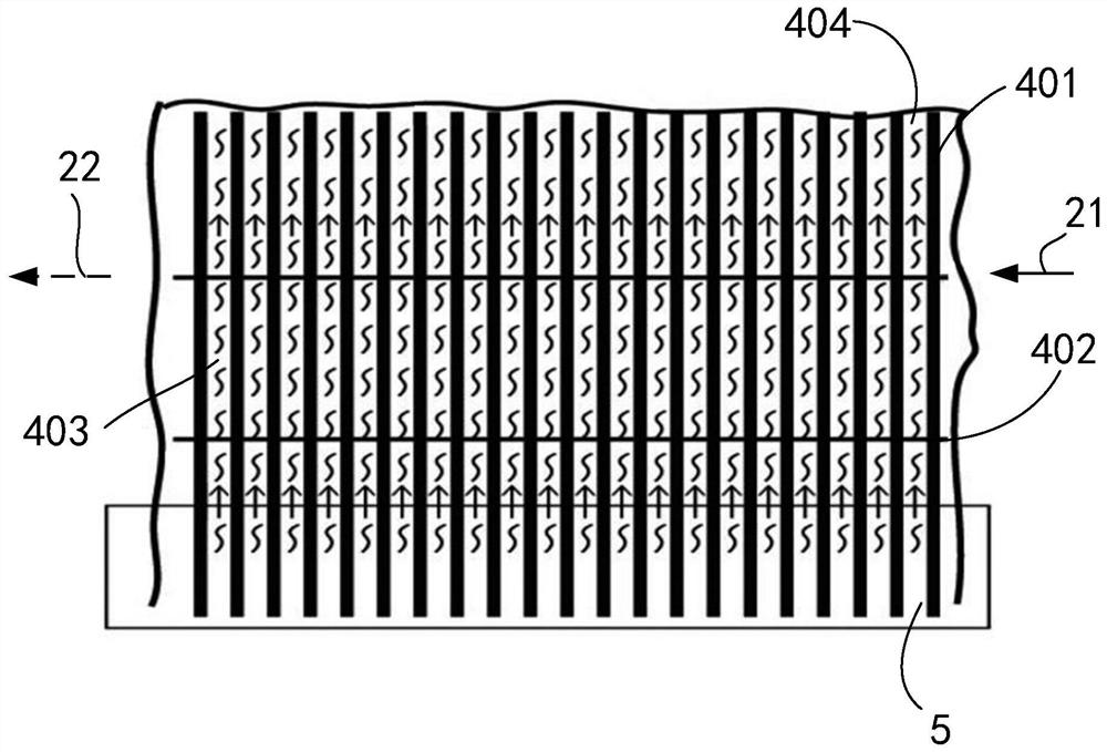
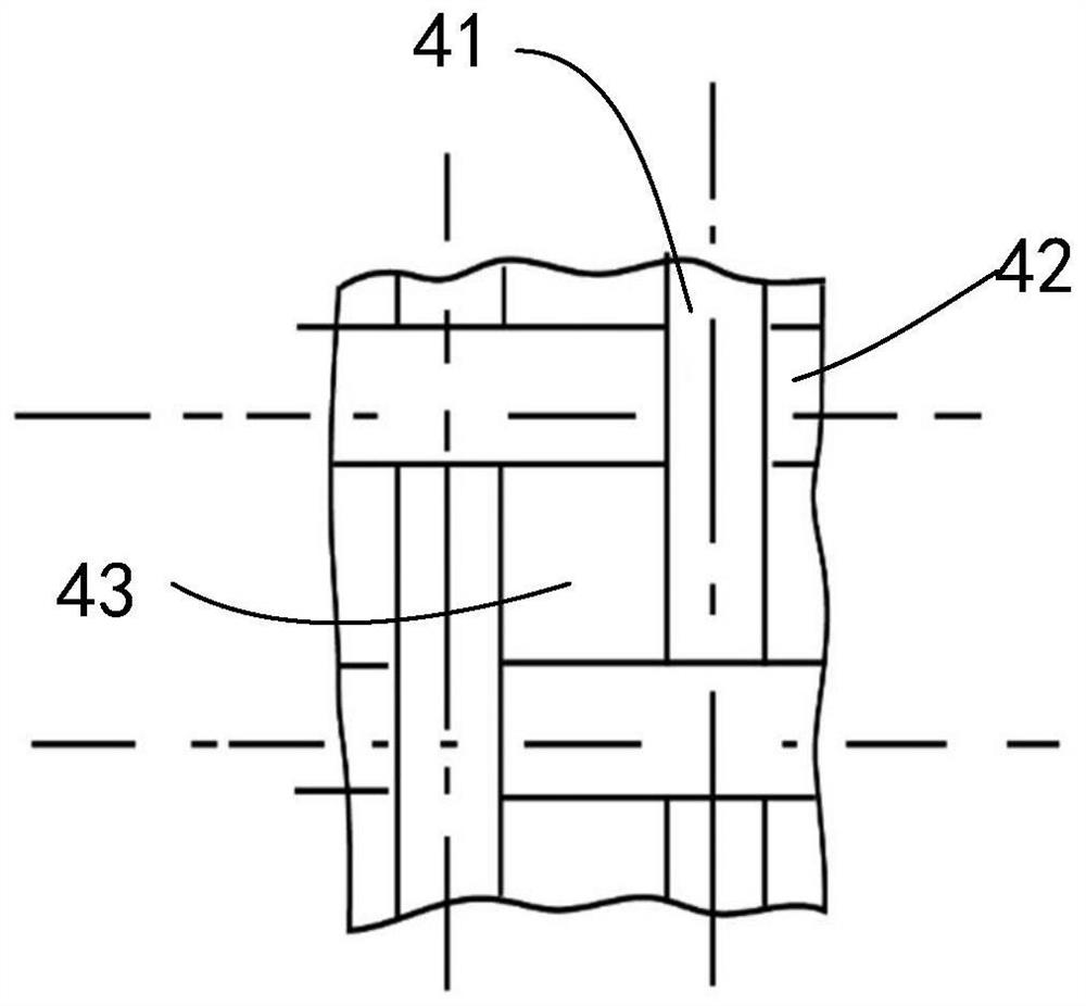
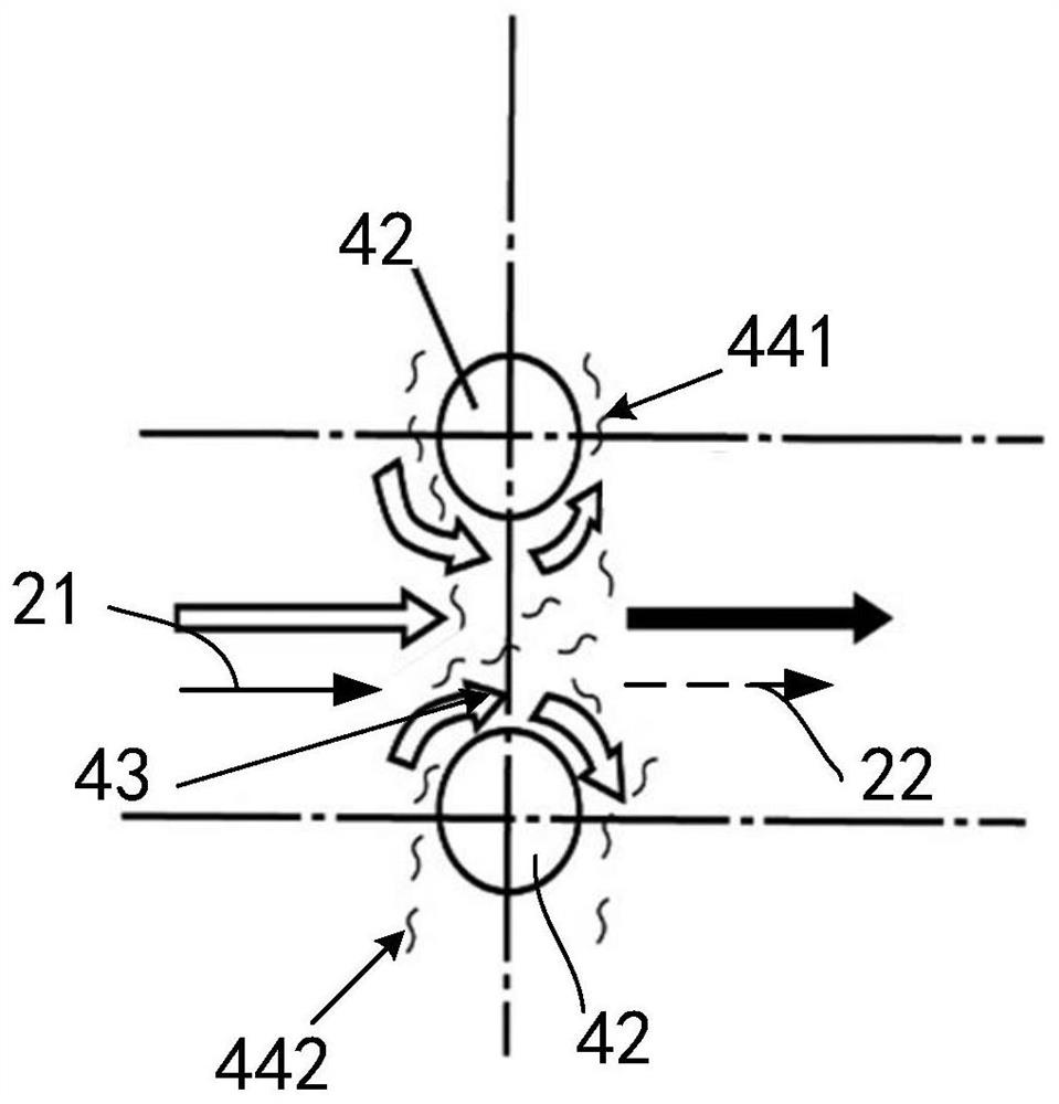
The gas purification device comprises a net rack which is rotationally arranged, at least part of the net rack is soaked in a solution pool so that fabric on part of the net rack can generate a soaking phenomenon, and a soaking liquid film is formed by means of liquid tension and used for purifying gas. According to the gas purification method for sterilization, the solution pool contains sterilization and disinfection substances to form a liquid film capable of sterilizing and disinfecting, and gas to be purified can sterilize and kill bacteria under the action of an infiltrating liquid film after penetrating through the infiltrating liquid film. Another gas purification device is provided, and an open-type wall-mounted liquid film can be formed by arranging a low-pressure nozzle and a high-low-pressure dual-purpose nozzle group. The invention provides a gas purification method for purifying oil fume, and oil stain cleaning is realized through a high-low pressure dual-purpose nozzle group and an oil-soluble solvent in the solution pool. The invention provides a capillary seam liquid film forming method which comprises the following steps: arranging multiple rows of plush warps in parallel to form capillary seams, immersing at least part of the plush warps into a solution, and enabling the solution to rise along the capillary seams by virtue of capillary action so as to form a seam liquid film.

Description

technical field [0001] The invention relates to the field of gas purification, in particular to the field of liquid membrane purification. Background technique [0002] At present, the air purification technologies mainly include wet packing layer filtration and purification, porous sieve plate purification, spray or spray purification, etc., but these liquid membrane purification methods still have obvious shortcomings: one is the micro Pores are easy to block, such as the liquid film grid used for flue gas purification on coal-fired furnaces. The diameter of the micropores on the grid is generally only about 1mm in diameter, and the particles in the polluted gas are of different sizes and shapes. During the process of passing through the micropores of the liquid membrane grid, the micropores are stuck in the micropores by larger dust particles, thereby blocking the airflow channel and making it difficult to clear. Generally, the liquid membrane grid or packing layer needs ...

Claims


Application Information

Patent Timeline
Patent Type & Authority Applications(China)
IPC IPC(8): B01D47/02B01D53/78B01D53/60
CPCB01D47/028B01D53/60B01D53/78B01D2257/91
Inventor 顾志龙顾晟华
Owner 顾志龙
Learn More