Eureka AIR delivers breakthrough ideas for toughest innovation challenges, trusted by R&D personnel around the world.

Integral casting prefabrication method for hollow beam slab

A hollow beam and bottom plate technology, used in manufacturing tools, ceramic molding mandrels, ceramic molding machines, etc., can solve the problems of long construction period and many processes, and achieve the effect of improving pouring efficiency and reducing processes

Active Publication Date: 2021-08-20
湖南省湘西公路桥梁建设有限公司
View PDF5 Cites 1 Cited by
  • Summary
  • Abstract
  • Description
  • Claims
  • Application Information

AI Technical Summary

Problems solved by technology

[0004] In view of the above-mentioned related technologies, the inventor believes that after demoulding, it is necessary to construct end-capping concrete to seal the end of the slab girder, and it is necessary to wait for the sealing concrete to completely solidify before it can be put into use. There are many procedures and a long construction period

Method used


Image

  • Integral casting prefabrication method for hollow beam slab
  • Integral casting prefabrication method for hollow beam slab
  • Integral casting prefabrication method for hollow beam slab

Examples


Embodiment 1

[0044] The embodiment of the present application discloses a prefabrication method for hollow beam slabs, which includes the following steps:

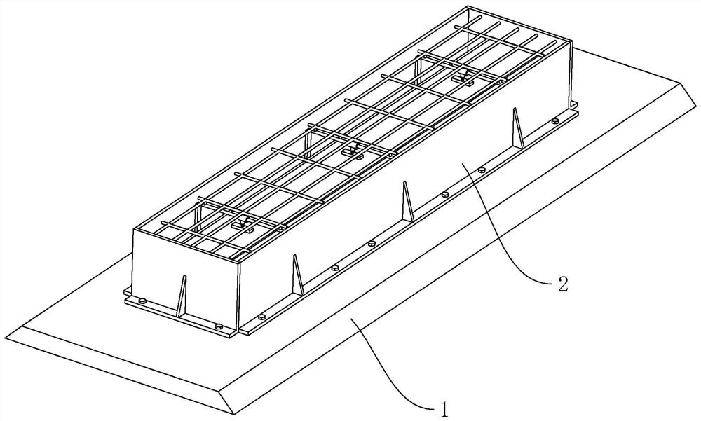
[0045] Step 1, refer to figure 1 and figure 2 , clean the base 1, the base 1 is a concrete mold in this embodiment, first wash and clean the dust and rust on the pedestal, and then apply a release agent on the base 1, generally 2 to 3 times, and apply Brush evenly to prevent the base 1 from sticking to the beam body, causing damage to the base 1.

[0046] Step 2: Fabricate and install the reinforcement frame of the bottom plate. 2. The grade and diameter of the reinforcement shall be manufactured in strict accordance with the requirements of the design documents. The reinforcement shall be connected by welding. The main reinforcement and other welded reinforcement shall be welded on both sides. Finally, install the bottom plate reinforcement frame 2 on the pedestal according to the design drawings.

[0047] Step 3, install formwork...

Embodiment 2

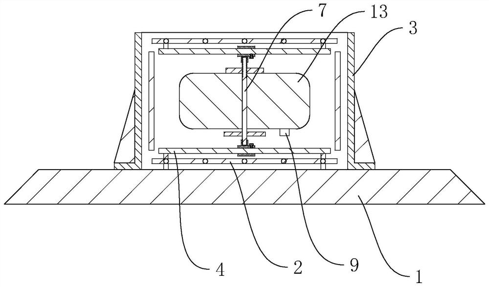
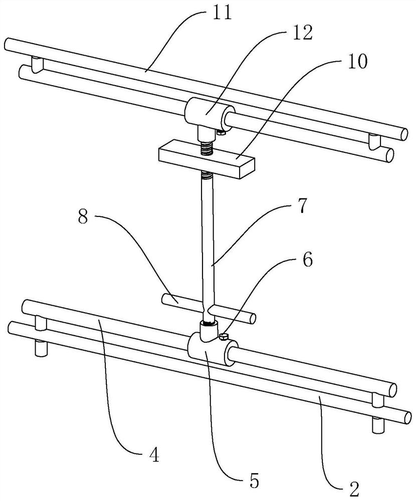
[0057] refer to Figure 4 and Figure 5 The difference between this embodiment and the first embodiment is that two sets of positioning rods 7 and mandrel positioning seats 5 are arranged along the width direction of the hollow beam slab, and the two positioning rods 7 are jointly installed at both ends of the same anti-floating plate 10 , the anti-floating plate 10 can slide along the axial direction of the positioning rod 7 . Locking nut 14 is threadedly connected on positioning bar 7, and anti-floating plate 10 is positioned between locking nut 14 and foam mandrel 13, and when screwing locking nut 14, locking nut 14 can be against the anti-floating plate 10 on On the foam mandrel 13. The corresponding top plate reinforcing bar frame 11 is also provided with two reinforcing bar positioning seats 12, and the reinforcing bar positioning seats 12 are plugged and matched with the positioning rods 7 one by one. By arranging two sets of positioning rods 7, the foam core mold 13...


PUM


Abstract

The invention relates to an integral casting prefabrication method for a hollow beam slab, and belongs to the field of bridge construction. The method comprises the following steps that 1, a base is cleaned, and a release agent is brushed on the base; 2, a bottom plate steel reinforcement framework is installed, and the bottom plate steel reinforcement framework is installed on a pedestal according to a design drawing; 3, a formwork is installed, the formwork is fixedly installed on the base, and the formwork surrounds the bottom plate steel reinforcement framework; 4, a concrete bottom plate is poured, the bottom plate steel reinforcement framework is filled with concrete, and the concrete bottom plate is formed; 5, a foam core mold is installed, the foam core mold is installed on the concrete bottom plate, and the foam core mold is fixed through an anti-floating part; 6, concrete side plates are poured, and the concrete is symmetrically poured on the two sides of the foam core mold in a balanced mode until the beam surface elevation is reached; and 7, a concrete top plate is poured, a top plate steel reinforcement framework is installed on the foam core mold, and then the concrete is poured. The method has the effects that the integral casting prefabrication process of the hollow beam slab is reduced, and the pouring efficiency is improved.

Description

technical field [0001] The present application relates to the field of bridge construction, in particular to a method for prefabricating hollow girder slabs. Background technique [0002] With the continuous development of the national economy, the role and status of road traffic in the national economy is becoming more and more prominent, and as a hub in road traffic—the bridge has also been greatly developed. The upper part of medium and small-span bridges mostly adopts prestressed and non-prestressed hollow beam-slab assembly structure. The hollow beam-slab structure is simple. It has the characteristics of convenient prefabrication, simple process, economical materials, easy factory and standardized production, convenient transportation and hoisting, and wide application range. [0003] Existing, the internal shape of the hollow beam slab is a rectangle with chamfers, which is similar to a small box girder. Due to the small internal size, if a steel inner mold is used,...

Claims


Application Information

Patent Timeline
Patent Type & Authority Applications(China)
IPC IPC(8): B28B7/30B28B7/38B28B13/02B28B23/02
CPCB28B13/02B28B23/022B28B7/30B28B7/384
Inventor 许可骄彭新林杨竹林伟田正钦
Owner 湖南省湘西公路桥梁建设有限公司
Why Eureka
Eureka Blog
Learn More