Cylindrical four-way powder distributing valve

A four-way material distribution, cylindrical technology, applied in the direction of conveying bulk materials, conveyors, slideways, etc., can solve the problems of inconvenient manufacturing, easy to increase resistance, etc., to facilitate processing and manufacturing, protect over-torque damage, avoid stacking effect

Inactive Publication Date: 2021-08-20
HANGZHOU FUYANG HENT ELECTROMECHANICAL ENG
View PDF7 Cites 1 Cited by
  • Summary
  • Abstract
  • Description
  • Claims
  • Application Information

AI Technical Summary

Problems solved by technology

[0004] In order to overcome the problem that the valve housing of the four-way distributing valve in the prior art is mainly shaped and formed by bending or welding several steel materials, it is inconvenient to manufacture, and there are various dead angles, which easily increase resistance and cause powder accumulation. Insufficient, provide a cylindrical powder four-way distributing valve, which is convenient for processing and manufacturing, can reduce internal resistance and reduce dead angle

Method used


Image

  • Cylindrical four-way powder distributing valve
  • Cylindrical four-way powder distributing valve
  • Cylindrical four-way powder distributing valve

Examples


Embodiment 1

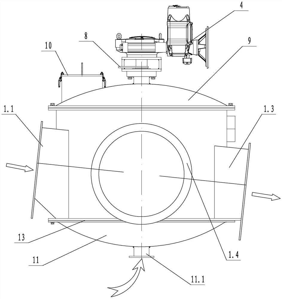
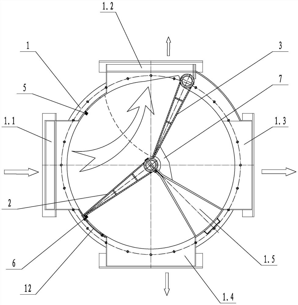
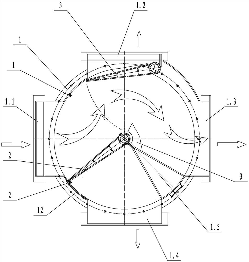
[0025] Such as Figures 1 to 4 As shown, a cylindrical powder four-way distributing valve includes a valve casing 1, a first swing door 2, a second swing door 3 and a driving member 4. The inner wall of the valve casing 1 is a cylindrical structure, A powder inlet 1.1, a first outlet 1.2, a second outlet 1.3 and a third outlet 1.4 are sequentially arranged on the side wall of the valve housing 1, the second outlet 1.3 and the third outlet 1.4 are separated by a partition 1.5, and the first pendulum The door 2 and the second swing door 3 are arranged in the valve casing 1 and are rotatably connected with the valve casing 1. One end of the rotation shaft of the first swing door 2 and the rotation shaft of the second swing door 3 stretches out of the valve casing 1 and is connected with the driving member. 4 is connected to the output end; the first swing door 2 is set on the side close to the powder inlet 1.1, the rotating shaft of the first swing door 2 is set at the center of ...

Embodiment 2

[0028] Such as figure 1As shown, on the basis of Embodiment 1, the bottom of the valve housing 1 is provided with an inflatable box 11, and the inflatable box 11 is provided with a suspension air inlet 11.1, and the inflatable box 11 and the bottom of the valve housing 1 pass through a partition and a breathable layer cloth. 13 separates, and is provided with several ventilation holes on the dividing plate and air-permeable layer cloth 13. The gas in the inflatable box 11 can enter the inside of the valve housing 1 to blow the material at the bottom of the valve housing 1 to prevent the material from accumulating in the valve housing 1 .

[0029] The beneficial effects of the present invention are: (1) convenient processing and manufacturing, which can reduce internal resistance and reduce dead angles, one inlet and two outlets of the distributing valve, one inlet and one outlet, and the other outlet has good sealing effect; It can effectively prevent over-opening and over-cl...


PUM


Abstract

The invention discloses a cylindrical four-way powder distributing valve which comprises a valve shell, a first swing door, a second swing door and a driving part, wherein the inner wall of the valve shell is of a cylindrical structure, a powder inlet, a first outlet, a second outlet and a third outlet are sequentially formed in the side wall of the valve shell, and the second outlet and the third outlet are separated through a partition part; the first swing door and the second swing door are arranged in the valve shell and rotationally connected with the valve shell. One end of a rotating shaft of the first swing door and one end of a rotating shaft of the second swing door extend out of the valve shell and are connected with the output end of the driving part; the first swing door is arranged on the side close to the powder inlet, the rotating shaft of the first swing door is arranged in the center of the valve shell, the second swing door is arranged between the first outlet and the second outlet, and the rotating shaft of the second swing door is arranged on the side close to the first outlet. The invention provides a cylindrical four-way powder distributing valve which is convenient to machine and manufacture and capable of reducing internal resistance and reducing dead angles.

Description

technical field [0001] The invention relates to the technical field of distributing valves, in particular to a cylindrical powder four-way distributing valve. Background technique [0002] The four-way distributing valve is an ideal device for controlling the rapid reversing of materials in the material conveying system. It is widely used in the transportation of solid particles and powders in industries such as building materials, metallurgy, mining, light industry, and grain. The four-way distribution valve is mainly composed of valve body, valve shaft, valve plate, crank mechanism, electric push rod (electro-hydraulic push rod or manual mechanism), etc. When working, the linear reciprocating motion of the electric and hydraulic push rods (manually by external force) drives the valve shaft and valve plate to swing at a certain angle through the crank, so as to achieve the purpose of controlling the flow of materials and distributing materials. The valve casing of the exis...

Claims


Application Information

Patent Timeline
Patent Type & Authority Applications(China)
IPC IPC(8): B65G53/46B65G53/66B65G11/20
CPCB65G53/46B65G53/66B65G11/206
Inventor 王永良
Owner HANGZHOU FUYANG HENT ELECTROMECHANICAL ENG
Why Eureka
Try Eureka