Shock insulation groove system of novel house building foundation shock insulation structure

A technology for foundation isolation and new housing, which is applied in the direction of infrastructure engineering, building components, buildings, etc., and can solve the problems that affect the free movement and damage of the superstructure, the isolation trench cover plate and the isolation trench retaining wall cannot slide freely, etc. question

Pending Publication Date: 2021-08-20
甘肃省建筑设计研究院有限公司
View PDF0 Cites 1 Cited by
  • Summary
  • Abstract
  • Description
  • Claims
  • Application Information

AI Technical Summary

Problems solved by technology

The cast-in-place cantilever type seismic isolation ditch cover has the following defects: (1) Although measures such as smooth surface and graphite powder coating are required in the design, there is often a gap between the movable prefabricated concrete slab and the concrete base due to reasons such as construction and later maintenance. Excessive friction hinders the large deformation of the seismic-isolation building theme under rare earthquakes; (2) During the building surface and water-spray construction, the construction personnel misunderstand the design or pay insufficient attention to the seismic-isolation structure, It is easy to cause the cover plate of the seismic isolation trench, the movable precast concrete slab and the upper

Method used


Image

  • Shock insulation groove system of novel house building foundation shock insulation structure
  • Shock insulation groove system of novel house building foundation shock insulation structure
  • Shock insulation groove system of novel house building foundation shock insulation structure

Examples


Embodiment Construction

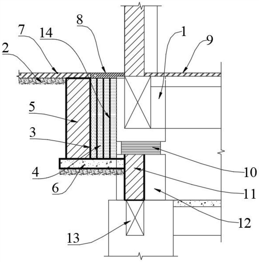
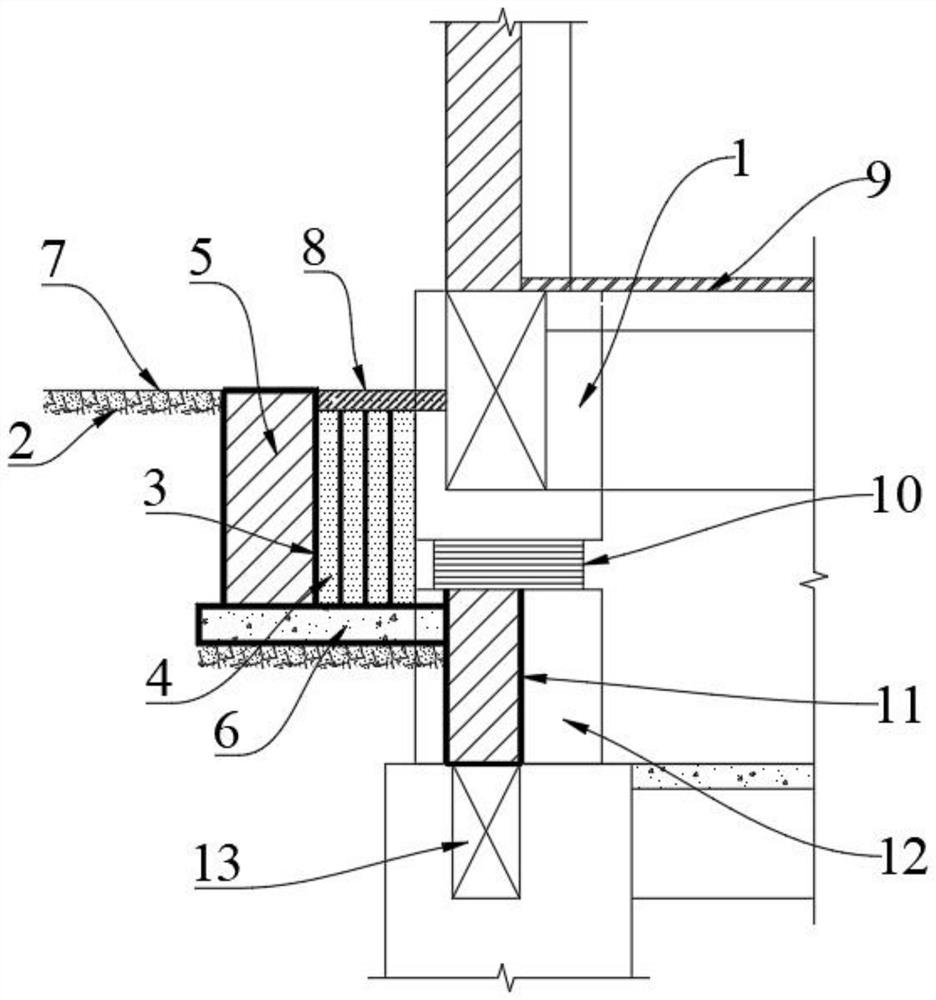
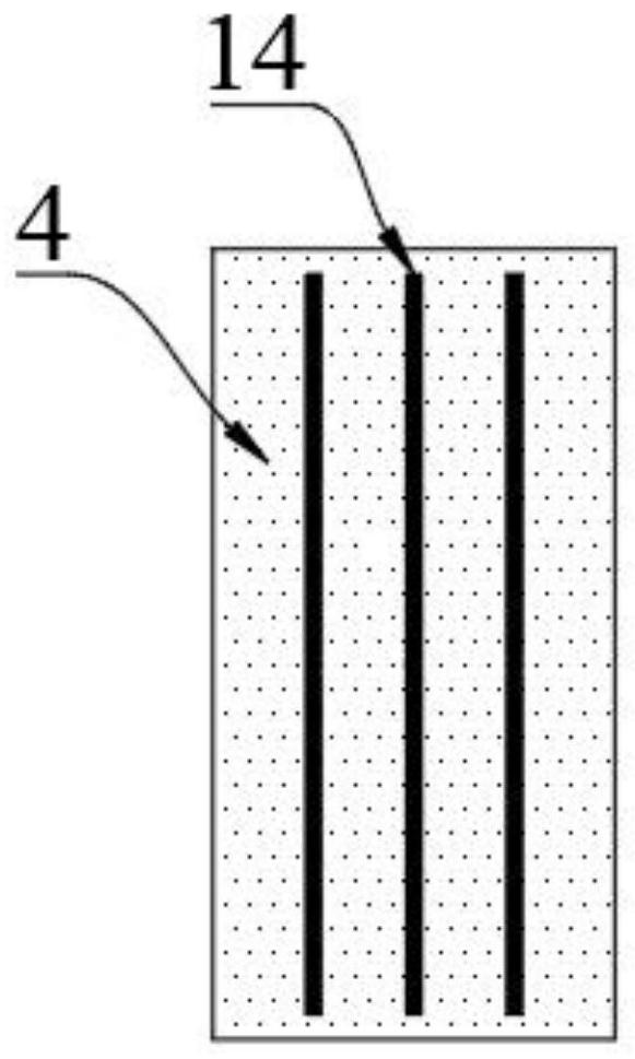
[0018] The present invention will be further described below in conjunction with accompanying drawing:

[0019] like Figure 1-3 As shown: the present invention includes a main body superstructure 1 of an earthquake-isolated building and a surrounding site fixture 2, and a leak-proof seismic isolation ditch 3 is vertically arranged between the main body superstructure 1 of the earthquake-isolated building and the surrounding site fixture 2, so that The bottom of the main superstructure 1 of the earthquake-isolation building is provided with an earthquake-isolation bearing and the lower pier 12. The leak-proof earthquake-isolation ditch 3 is provided with an earthquake-isolation ditch retaining wall 5, and the bottom of the main superstructure 1 of the earthquake-isolation building is arranged There is an underground outer wall 11, the lower end of the underground outer wall 11 is provided with a foundation 13, and an earthquake-isolation support is arranged between the lower e...


PUM


Abstract

The invention discloses a shock insulation groove system of a novel house building foundation shock insulation structure. The shock insulation groove system comprises a leakage-proof shock insulation groove formed between a shock insulation building body and a peripheral fixture, a shock insulation groove retaining wall, an underground outer wall, a reinforced concrete cushion layer at the bottom of the shock insulation groove, and a one-way compression laminated polystyrene foam filling body stuffed in the shock insulation groove, wherein the shock insulation groove retaining wall and the underground outer wall are arranged in the shock insulation groove. The shock insulation groove system has very high horizontal compression performance and necessary vertical strength and rigidity, so that the seismic isolation groove system can freely move in the horizontal direction under the action of an earthquake and can vertically meet the requirement for passing of personnel. The shock insulation groove system has the advantages that the industrialization degree is high, mounting and construction are easy, misoperation of constructors is reduced, the construction speed is increased, it is guaranteed that the upper structure of the shock insulation building body and a peripheral site fixture 2 can freely deform, and the shock insulation efficiency of the shock insulation structure is improved.

Description

technical field [0001] The invention relates to the field of building foundation shock-isolation engineering, in particular to a novel shock-isolation ditch system for building foundation shock-isolation structures. Background technique [0002] As a natural disaster, earthquake has caused huge disasters to human beings many times in history. In recent years, with the continuous deepening of the research on shock absorption and isolation technology for construction engineering, engineering application work has been carried out in some high-seismic areas in my country. The safety of people's life and property has produced good social benefits. Practice has proved that shock absorption and isolation technology can effectively reduce the effect of earthquakes and improve the anti-seismic fortification capacity of building construction projects. [0003] Base isolation is one of the earlier researched, more mature and widely used technologies in the seismic isolation technology...

Claims


Application Information

Patent Timeline
IPC IPC(8): E02D31/08E04H9/02E04B1/98
CPCE02D31/08E04B1/98E04H9/021
Inventor 王沛钦黄锐江重阳张宏颖姚佩歆杨春娟
Owner 甘肃省建筑设计研究院有限公司
Why Eureka
Try Eureka