Chemical fiber production sewage comprehensive treatment device
A production sewage and comprehensive treatment technology, applied in water/sewage treatment, water/sewage multi-stage treatment, water/sludge/sewage treatment, etc., can solve problems such as hazards, chemical fiber production sewage pollution, human health, microbial toxicity, etc. , to achieve the effect of increasing the processing rate
- Summary
- Abstract
- Description
- Claims
- Application Information
AI Technical Summary
Problems solved by technology
Method used
Image
Examples
Embodiment 1
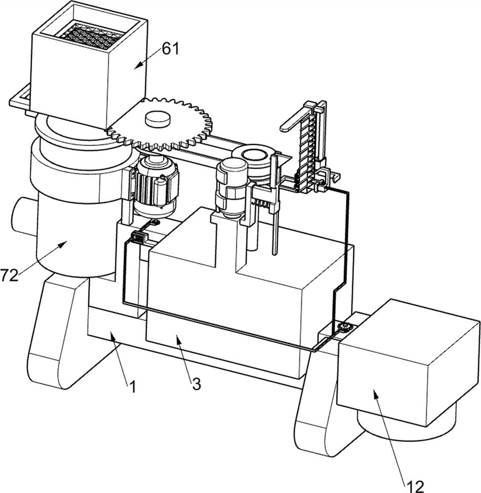
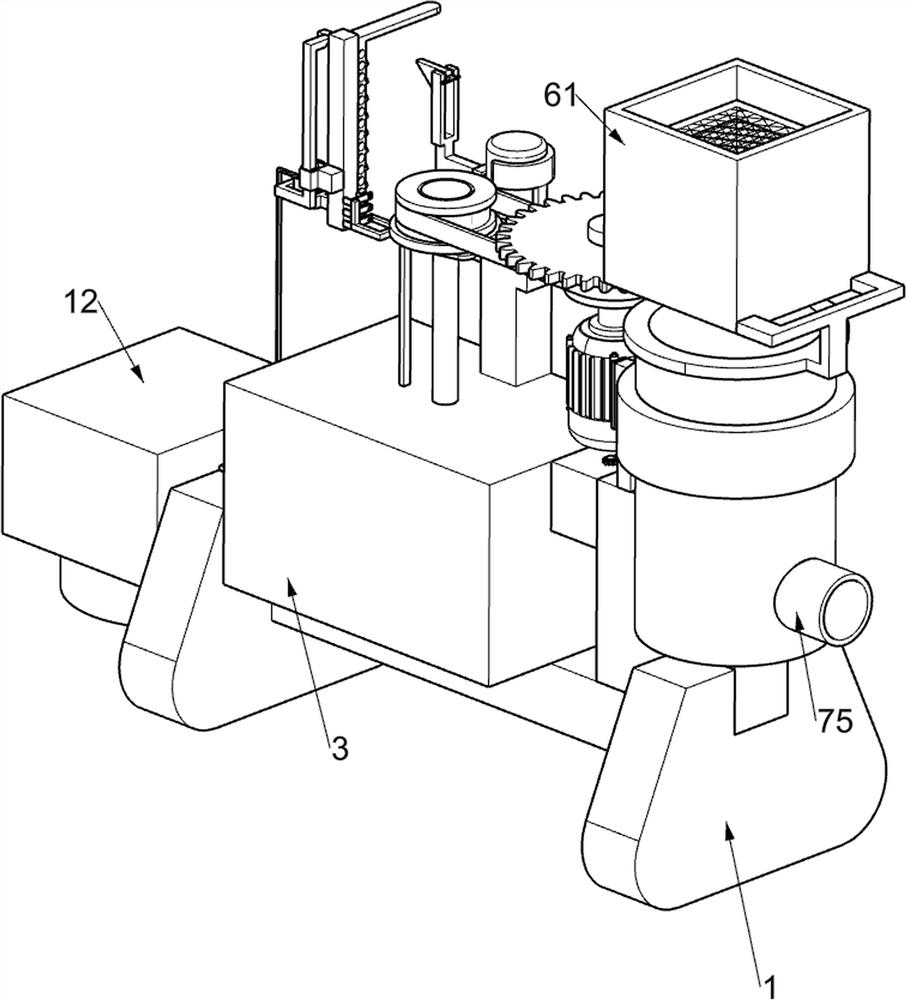
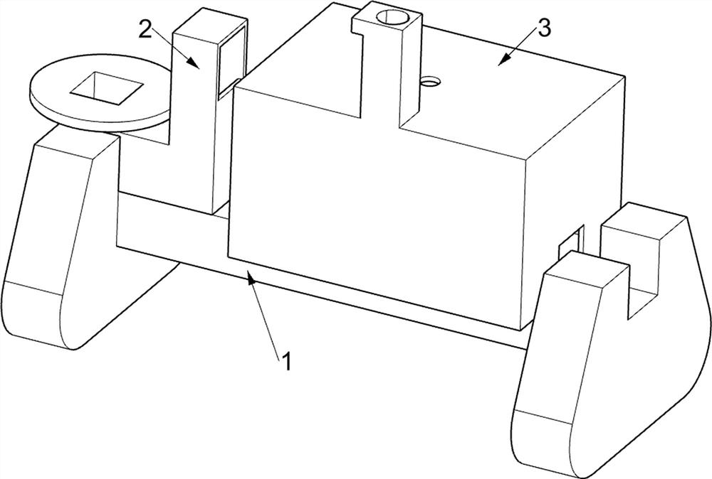
[0040] Chemical fiber production sewage comprehensive treatment device, such as Figure 1-9 As shown, it includes a fixed base 1, a special-shaped water injection pipe 2, a reaction tank 3, a gate opening mechanism 4, and a stirring mechanism 5. A special-shaped water injection pipe 2 for transporting sewage from chemical fiber production is fixedly installed on the upper left of the fixed base 1. Above the fixed base 1 A reaction pool 3 is fixedly connected, and the interior of the reaction pool 3 is a cavity structure. The reaction pool 3 is located on the right side of the special-shaped water injection pipe 2. The reaction pool 3 is equipped with a delivery gate mechanism 4 for controlling the sewage produced by chemical fiber. Above the special-shaped water injection pipe 2 A stirring mechanism 5 for fully stirring the chemical fiber production sewage and sodium hypochlorite in the reaction tank 3 is provided.
[0041] Opening mechanism 4 includes short valve body 41, L-s...
Embodiment 2
[0045] On the basis of Example 1, such as Figure 10-11 As shown, it also includes a deoiling mechanism 7, the deoiling mechanism 7 is located on the motor support ring 51, and the deoiling mechanism 7 used to separate the oil and water in the chemical fiber production sewage includes a gear 2 71, a special-shaped perforated pipe 72. Gear 3 73, perforated rotating cylinder 74 and filter oil pipe 75, gear 2 71 is fixedly connected to the short shaft 53, special-shaped perforated tube 72 is fixedly connected to the motor support ring 51, and the internal rotation of the special-shaped perforated tube 72 is connected There is a perforated rotary cylinder 74, the perforated rotary cylinder 74 is cylindrical and its lower part is conical, the perforated rotary cylinder 74 is located inside the special-shaped perforated tube 72, and the top of the perforated rotary cylinder 74 is connected with a gear three 73, and the gear three 73 meshes with the second gear 71, the third gear 73 ...
Embodiment 3
[0049] On the basis of Example 2, such as Figure 12-15 As shown, it also includes a pressing mechanism 8, and the pressing mechanism 8 is located on the special-shaped turret 55. The pressing mechanism 8 includes a cam 81, a T-shaped push rod 82, a third return spring 83, a wedge-shaped block 84 and the first Four return springs 85, the upper part of the major axis 59 is fixedly connected with a cam 81, and the top of the special-shaped turret 55 is slidably connected with a T-shaped push rod 82, the T-shaped push rod 82 is located on the right side of the cam 81, and the T-shaped push rod 82 is in contact with the cam 81 , the third return spring 83 for driving the T-shaped push rod 82 to reset is connected between the T-shaped push rod 82 and the special-shaped turret 55, and the T-shaped push rod 82 is slidably connected with a push wedge-shaped block 84, which promotes the wedge-shaped block 84 and A fourth return spring 85 is connected between the T-shaped push rods 82 f...
PUM
 Abstract
Description
Claims
Application Information
 - R&D
- Intellectual Property
- Life Sciences
- Materials
- Tech Scout
- Unparalleled Data Quality
- Higher Quality Content
- 60% Fewer Hallucinations
Browse by: Latest US Patents, China's latest patents, Technical Efficacy Thesaurus, Application Domain, Technology Topic, Popular Technical Reports.
© 2025 PatSnap. All rights reserved.Legal|Privacy policy|Modern Slavery Act Transparency Statement|Sitemap|About US| Contact US: help@patsnap.com


