Transition structure from microstrip line to non-radiation dielectric waveguide

A dielectric waveguide and transition structure technology, applied in the millimeter wave field, can solve the problems of low purity, unfavorable for integration process, affecting NRD waveguide transmission, etc., achieve good bandwidth characteristics, facilitate integrated applications, and require low processing and assembly accuracy. Effect

Inactive Publication Date: 2021-08-31
UNIV OF ELECTRONICS SCI & TECH OF CHINA
View PDF5 Cites 6 Cited by
  • Summary
  • Abstract
  • Description
  • Claims
  • Application Information

AI Technical Summary

Problems solved by technology

This kind of incentive method is for the motivated LSM 01 Mode (NRD waveguide main mode) purity is not high, affecting the transmission of NRD waveguide
At the same ti...

Method used


Image

  • Transition structure from microstrip line to non-radiation dielectric waveguide
  • Transition structure from microstrip line to non-radiation dielectric waveguide
  • Transition structure from microstrip line to non-radiation dielectric waveguide

Examples


Embodiment Construction

[0028] In order to make the technical means and advantages of the present invention clearer, the present invention will be further described in detail below in conjunction with specific embodiments and with reference to the accompanying drawings.

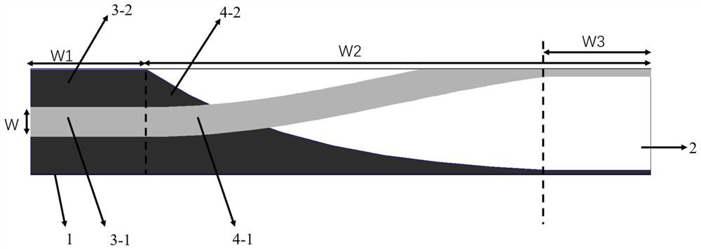
[0029] For the transition structure provided in this embodiment, see figure 1 , Figure 5 , the transition structure includes a microstrip line transmission section-double ridge fin line transformation section-gradient horn section connected in sequence.

[0030] The transmission section of the microstrip line is a 50Ω standard microstrip line, including the first rectangular dielectric substrate (1), the narrow side metal patch (3-1) on the front side of the first rectangular dielectric substrate, and the broad side on the back side of the first rectangular dielectric substrate Metal patch (3-2). The width W of the narrow side metal patch (3-1) is 0.76mm, and the width W of the wide side metal patch (3-2), the first and the secon...


PUM


Abstract

The invention discloses a transition structure from a microstrip line to a non-radiation dielectric waveguide, which belongs to the technical field of millimeter waves. According to the structure, sequential transition of a pre-stage device, a microstrip transmission section, a double-ridge fin line conversion section and a gradually-changed horn section-NRD waveguide is adopted, and coaxial line TEM signals are input into the microstrip transmission section to transmit a quasi-TEM mode; the signal is input into a double-ridge fin line conversion section, and converted from a quasi-TEM mode to a rectangular waveguide TE10 mode which deflects by 90 degrees in a polarization direction; and the signal passes through the gradually-changed horn section to generate a plurality of high-order rectangular waveguide modes, and finally an LSM01 mode of NRD waveguide transmission is formed. The structure has a good bandwidth characteristic and is suitable for integrated application in a system.

Description

technical field [0001] The invention belongs to the technical field of millimeter waves, and in particular relates to a transition structure from a microstrip line to a non-radiative medium waveguide realized by a microstrip line transition section-double ridge fin line transformation section-a gradual horn section. Background technique [0002] With the deepening of social informatization, the microwave spectrum is becoming more and more crowded. Communication needs larger capacity, wider frequency band and higher speed information processing, exchange and transmission capabilities. Millimeter wave is prepared for its short wavelength and wide frequency bandwidth. favored. However, in the millimeter wave frequency band, due to its high operating frequency, the loss of the transmission structure will be relatively large. Therefore, the loss factor is the primary consideration when selecting a millimeter-wave transmission structure. [0003] At present, commonly used transm...

Claims


Application Information

Patent Timeline
IPC IPC(8): H01P5/10
CPCH01P5/10
Inventor 李浩欧美玲吴鑫磊
Owner UNIV OF ELECTRONICS SCI & TECH OF CHINA
Why Eureka
Try Eureka