Underwater wireless optical communication system based on partial response shaping technology and TCM technology
A wireless optical communication and partial response technology, applied in baseband systems, optical transmission systems, baseband system components, etc., can solve problems such as signal-to-noise ratio degradation and amplified noise
- Summary
- Abstract
- Description
- Claims
- Application Information
AI Technical Summary
Problems solved by technology
Method used
Image

Examples
Embodiment Construction
[0040] The present invention is described in detail below in conjunction with accompanying drawing;
[0041] First of all, it should be noted that all electronic components (components) used in the present invention are mature technologies, and there are corresponding commercially available products. On the basis of reading and understanding the application documents, those skilled in the art can fully reproduce the present invention according to their software radio knowledge and various digital signal processing skills;
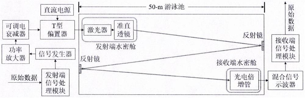
[0042] Such as figure 1 As shown, the underwater wireless optical communication system based on partial response shaping technology and TCM technology, including signal generator, power amplifier, adjustable electrical attenuator, T-type bias device, DC power module, laser, collimating lens, transmitting Terminal watertight cabin, reflector, photomultiplier tube, mixed signal oscilloscope, receiving terminal watertight cabin, transmitting terminal signal ...
PUM
 Abstract
Description
Claims
Application Information