Auxiliary device for wart cutting in dermatology department
An auxiliary device and dermatological technology, applied in the field of dermatology, can solve the problem of inconvenient cutting of warts, achieve the effect of good flushing effect and ensure safety
- Summary
- Abstract
- Description
- Claims
- Application Information
AI Technical Summary
Problems solved by technology
Method used
Image
Examples
Embodiment 1
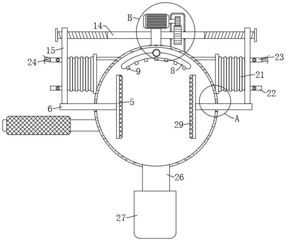
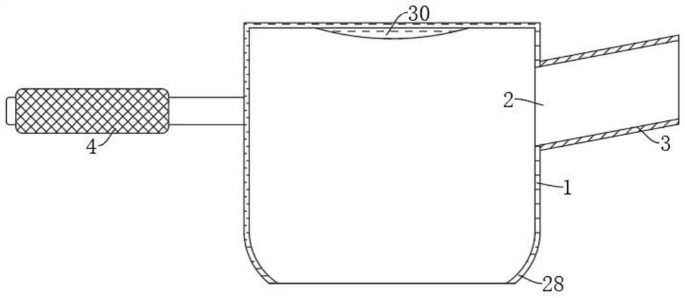
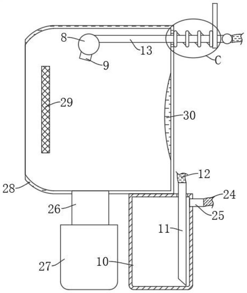
[0031] refer to Figure 1-6 , an auxiliary device for wart cutting in dermatology, comprising a cylindrical transparent cover 1, and further comprising: a handle 4 fixedly mounted on the outer wall of the cylindrical transparent cover 1; an operation groove 2 arranged on the outer wall of the cylindrical transparent cover 1, Among them, the operation tube 3 installed obliquely is fixedly installed in the operation groove 2; two symmetrically arranged splints 5 are arranged in the cylindrical transparent cover 1, and are connected with the cylindrical transparent cover 1 through a clamping mechanism for clamping The place to be cut; the side wall is provided with the nozzle 8 of the nozzle 9, which is arranged in the cylindrical transparent cover 1, and is connected with the cylindrical transparent cover 1 through an adjustment mechanism, and is used to adjust the position of the nozzle 8, which can be adjusted by the clamping mechanism. The wart is lifted up to make the cuttin...
Embodiment 2
[0036] refer to figure 1 , Figure 4 and Figure 5 , is basically the same as Embodiment 1, furthermore: the clamping mechanism includes a double-ended threaded rod 14 that is rotatably installed on the side wall of the cylindrical transparent cover 1, and the two ends of the double-ended threaded rod 14 have opposite thread directions, and the double-ended threaded rod 14 Both ends of 14 are threadedly connected with threaded slides 15, and the opposite side walls of the two threaded slides 15 are fixedly connected with push rods 6, and both sides of the cylindrical transparent cover 1 are respectively provided with sliding holes that cooperate with the two push rods 6. 7. The two push rods 6 are slidably connected in the two slide holes 7 respectively, and the two splints 5 are fixedly installed on the ends of the two push rods 6 respectively. The outer wall of the cylindrical transparent cover 1 is fixedly installed with a motor 16, and the motor 16 The output end and the...
Embodiment 3
[0039] refer to image 3 and Image 6 , is basically the same as Embodiment 1, furthermore: the adjustment mechanism includes a delivery pipe 13 fixedly connected to the side wall of the nozzle 8, the side wall of the delivery pipe 13 is fixedly equipped with a valve, and the top side wall of the cylindrical transparent cover 1 is provided with There is a through hole 18, and the conveying pipe 13 is slidably connected to the through hole 18. The outer wall of the end of the conveying pipe 13 is fixedly connected with a push plate 19, and the push plate 19 is elastically connected to the outer wall of the cylindrical transparent cover 1 through a return spring 20. A water tank 10 is fixedly installed on the side wall of the transparent cover 1, and the upper end of the water tank 10 is fixedly connected with a pipe body 11 with an inner bottom. The side wall of the cylindrical transparent cover 1 is provided with a drain pipe 26 communicating with it, and the liquid discharge...
PUM
 Abstract
Description
Claims
Application Information
 - R&D
- Intellectual Property
- Life Sciences
- Materials
- Tech Scout
- Unparalleled Data Quality
- Higher Quality Content
- 60% Fewer Hallucinations
Browse by: Latest US Patents, China's latest patents, Technical Efficacy Thesaurus, Application Domain, Technology Topic, Popular Technical Reports.
© 2025 PatSnap. All rights reserved.Legal|Privacy policy|Modern Slavery Act Transparency Statement|Sitemap|About US| Contact US: help@patsnap.com


