Single-pole double-throw coplanar waveguide type radio frequency mechanical switch structure

A coplanar waveguide, single-pole double-throw technology, applied in the direction of waveguide-type devices, electrical components, circuits, etc., can solve the problem of miniaturization, integration indicators cannot form a qualitative breakthrough, and the size of the switch body cannot be miniaturized and improved. requirements and other issues, to achieve the effects of miniaturization, size reduction, and low insertion loss

Pending Publication Date: 2021-09-03
中国电子科技集团公司第四十研究所
View PDF0 Cites 0 Cited by
  • Summary
  • Abstract
  • Description
  • Claims
  • Application Information

AI Technical Summary

Problems solved by technology

Simplify and compress the structure of each component, but limited by the size of the connector interface, the anti-vibration performance design of the moving parts, and the requirements for high power indicators, the miniaturization and integration indicators cannot form a qualitative breakthrough
[0005] The existing RF mechanical switch replaces the traditional standard connector size interface with solder pins, which effectively reduces the overall size of the switch, but the size of the switch body cannot be miniaturized and improved
Under the development trend of miniaturization of the whole machine system, it still cannot meet the requirements

Method used


Image

  • Single-pole double-throw coplanar waveguide type radio frequency mechanical switch structure
  • Single-pole double-throw coplanar waveguide type radio frequency mechanical switch structure
  • Single-pole double-throw coplanar waveguide type radio frequency mechanical switch structure

Examples


Embodiment Construction

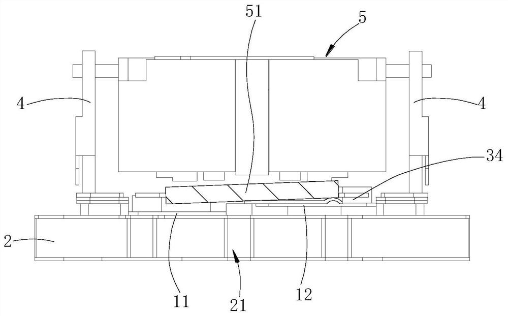
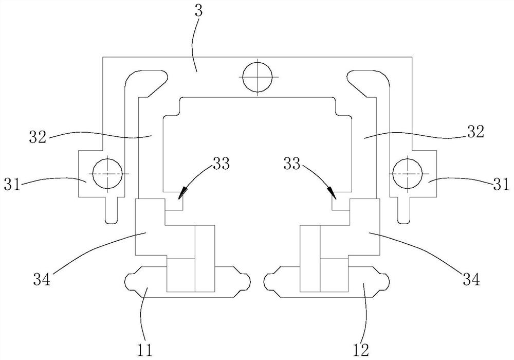
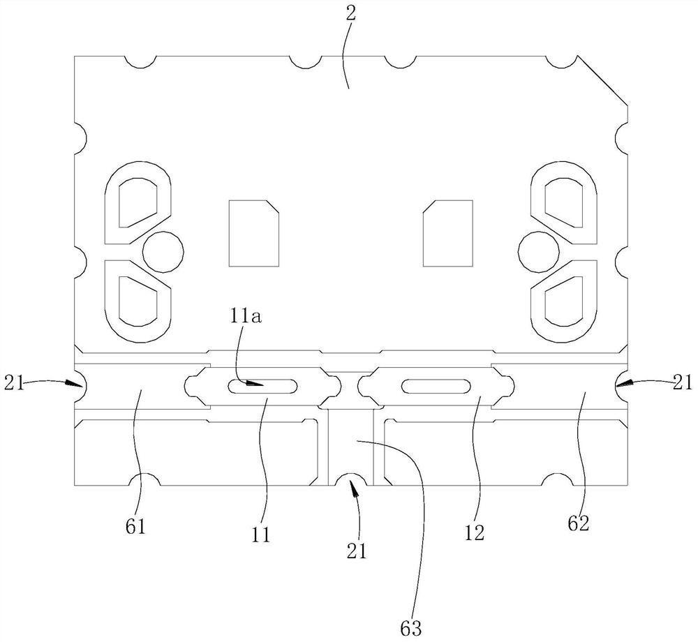
[0025] Such as Figures 1 to 3 shown.

[0026] The switch structure includes a radio frequency substrate 2, a transmission reed 3, two radio frequency reeds and three microstrip pieces.

[0027] The two RF reeds are hard gold plated on the surface of beryllium copper material, the two RF reeds are respectively the first RF reed 11, the second RF reed 12, the structure of the first RF reed 11 and the second RF reed 12 Similarly, taking the first radio frequency reed 11 as an example, the first radio frequency reed 11 includes a horizontal plate body and a vertical portion, the upper end of the horizontal plate body has an assembly groove 11a, and the assembly groove 11a extends into the vertical portion.

[0028] The RF substrate 2 adopts Rogers 4003 board, which is coated with copper on both sides and then gold-plated. Three microstrips are respectively welded on the RF substrate 2. The three microstrips are independent of each other. The three microstrips are J1 microstrips ...


PUM


Abstract

The invention provides a single-pole double-throw coplanar waveguide type radio frequency mechanical switch structure. The switch structure comprises a radio frequency substrate, a transmission reed, two radio frequency reeds and three microstrip sheets, wherein the two radio frequency reeds are respectively a first radio frequency reed and a second radio frequency reed, the three microstrip pieces are respectively fixed on the radio frequency substrate, and the three microstrip pieces are mutually independent; the transmission reed is fixedly connected to the radio frequency substrate, the transmission reed extends towards the microstrip pieces to form two front extending arms, ends of the two front extending arms are located on the upper sides of the three microstrip pieces respectively, stress points matched with an electromagnetic system are arranged on the two front extending arms respectively, and the first radio frequency reed and the second radio frequency reed are arranged on the lower sides of the two front extending arms respectively. According to the switch structure, a circular coaxial transmission line and a rectangular transmission line of a traditional radio frequency mechanical switch are replaced by microstrip surfaces of a coplanar waveguide structure, more reliable welding type installation is adopted, the size of the radio frequency mechanical switch is greatly reduced, and meanwhile it is guaranteed that the radio frequency mechanical switch structure has the advantages of being high in linearity, low in insertion loss and high in power resistant index.

Description

technical field [0001] The invention relates to a single pole double throw coplanar waveguide type radio frequency mechanical switch structure. Background technique [0002] The radio frequency mechanical switch is mainly composed of three parts: signal control system, electromagnetic conversion system and microwave transmission system. The microwave transmission system is the actuator to realize microwave signal transmission / switching, and is the core of the radio frequency mechanical switch. An excellent microwave transmission system is the key to realize the high performance of the relay. The microwave transmission system of the traditional switch is composed of a rectangular transmission line microwave cavity and a circular coaxial transmission line connector assembly. The external dimensions of this type of radio frequency mechanical switch greatly restrict the development of products. [0003] The miniaturization design of the RF mechanical switch structure has been ...

Claims


Application Information

Patent Timeline
Patent Type & Authority Applications(China)
IPC IPC(8): H01P1/12
CPCH01P1/12
Inventor 盛金月尹沃良刘贝杨倩
Owner 中国电子科技集团公司第四十研究所
Why Eureka
Try Eureka