
Drying system and drying method for large workpieces

A technology for drying systems and large workpieces, which is applied in the direction of pretreatment of surfaces, coatings, devices for coating liquids on surfaces, etc., and can solve problems such as low drying efficiency, large energy consumption, and low drying efficiency

Pending Publication Date: 2021-09-07
苏州开泰利环保能源有限公司
View PDF7 Cites 0 Cited by
  • Summary
  • Abstract
  • Description
  • Claims
  • Application Information

AI Technical Summary

Problems solved by technology

[0003] However, when drying some large and heavy irregular workpiece equipment such as large mechanical arms or oil tanks, they are all dried by hot air drying technology, and the air temperature in the drying chamber is reduced by using hot air drying. Gradually increase, and then heat the product to be dried through heat transfer. Although this heating method can achieve a better drying effect, the drying efficiency is low and the drying energy consumption is high. It is necessary to gradually increase the air temperature in the chamber. And after a product is dried, open the chamber doors on both sides and replace new workpieces for drying, the airflow on both sides of the chamber will convect, resulting in a large amount of heat loss, the temperature in the chamber will drop, and the temperature in the chamber will be dried by hot air again. , large energy loss and high cost, which is too expensive for enterprises
[0004] Although in the existing infrared drying technology, the product is directly heated and dried by infrared drying, when drying some products with ink sprayed on the surface, the required heating temperature is high. For general infrared drying The method requires a long drying time, low drying efficiency, and infrared drying is by directly drying the surface of the product, which cannot achieve uniform drying on the surface of irregular structure products, so the existing infrared drying technology does not Suitable for drying of this type of product

Method used


Image

  • Drying system and drying method for large workpieces

Examples


Embodiment Construction

[0033] The technical solutions in the embodiments of the present invention will be clearly and completely described below with reference to the accompanying drawings in the embodiments of the present invention. Obviously, the described embodiments are only a part of the embodiments of the present invention, but not all of the embodiments. Based on the embodiments of the present invention, all other embodiments obtained by those of ordinary skill in the art without creative efforts shall fall within the protection scope of the present invention.

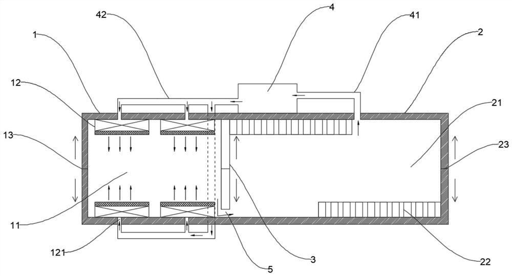
[0034] like figure 1 Shown is a drying system for large workpieces, including a preheating part 1 and a heat preservation part 2, the preheating part 1 includes a preheating chamber 11 and a plurality of high-power infrared rays arranged on the inner wall of the preheating chamber 11. The light-emitting panel 12, the plurality of high-power infrared light-emitting panels 12 are gas-catalyzed infrared light-emitting panels;

[0035] T...


PUM


Abstract

The invention discloses a drying system and a drying method for large workpieces. The drying system comprises a preheating part and a heat preservation part, and the preheating part comprises a preheating cavity and a plurality of high-power infrared light-emitting plates in the preheating cavity; the heat preservation part comprises a heat preservation cavity and a heat supply assembly used for heating air in the heat preservation cavity; the preheating cavity communicates with the heat preservation cavity, and a bin door is arranged between the preheating cavity and the heat preservation cavity; and an air draft unit is arranged outside the preheating part and the heat preservation part. The surface of a workpiece is rapidly heated and dried at high temperature through the preheating part, then the workpiece is moved into the heat preservation part to be subjected to heat preservation and drying, in the working process, gas in the heat preservation cavity is extracted into the preheating cavity through the air draft unit, sufficient reaction oxygen is provided for the preheating part, meanwhile, heat is provided, and heat loss is reduced. The drying device is simple in structure, low in manufacturing cost, obviously high in drying efficiency, capable of guaranteeing the drying effect and reducing energy loss, energy-saving and environment-friendly.

Description

technical field [0001] The invention relates to the technical field of drying, in particular to a drying system and a drying method for large workpieces. Background technique [0002] With the development of industrial technology, drying technologies are becoming more and more diversified. Generally, the workpiece products are dried by using the corresponding drying system. The drying system refers to the drying of moisture or other liquids on the surface of objects through certain technical means. A combination of a series of mechanical equipment. Popular drying technologies are mainly UV drying, infrared drying, electromagnetic drying and hot air drying. [0003] However, when drying some large and heavy irregular workpieces and equipment such as large robotic arms or oil tanks, they are all dried by hot air drying technology. By using hot air drying, the air temperature in the drying chamber is changed. Gradually increase, and then heat the product to be dried through h...

Claims


Application Information

Patent Timeline
IPC IPC(8): B05D3/02B05D3/04
CPCB05D3/0209B05D3/0263B05D3/0413Y02P70/10
Inventor 潘嵩贾卓王统照李磊王天倪旻睿于浩玮刘奕巧
Owner 苏州开泰利环保能源有限公司
Learn More