
Environment-friendly bottle body recycling equipment

A recycling equipment and an environmentally friendly technology, applied in the field of environmentally friendly bottle body recycling equipment, can solve the problems of inconvenient promotion and use, difficult to remove the adhesive area of ​​packaging tape, affecting the working environment, etc.

Active Publication Date: 2021-09-07
徐州虹源环保科技有限公司
View PDF6 Cites 0 Cited by
  • Summary
  • Abstract
  • Description
  • Claims
  • Application Information

AI Technical Summary

Problems solved by technology

[0003] In the recycling process of existing plastic bottles, the packaging tape on the plastic bottle is generally broken and separated after the sorting is completed, and then the damaged packaging tape is blown out by a fan, but it is difficult to remove the adhesive area on the packaging tape , resulting in the need for manual re-screening after the plastic bottle is broken, and the debris produced by the broken packaging tape will also affect the working environment, and may be mixed in the plastic bottle debris, affecting subsequent operations, which is unreasonable and not easy to promote use

Method used


Image

  • Environment-friendly bottle body recycling equipment
  • Environment-friendly bottle body recycling equipment
  • Environment-friendly bottle body recycling equipment

Examples


Embodiment 1

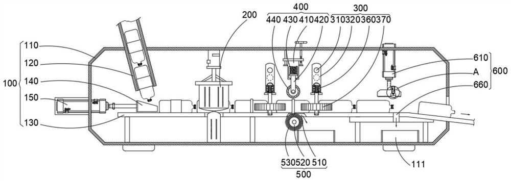
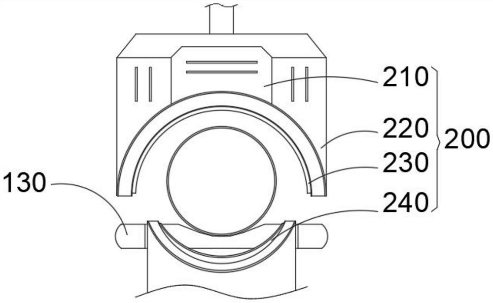
[0045] combine Figure 1-8As shown, the environment-friendly bottle recovery equipment provided by the present invention includes: a feeding mechanism 100, a blanching mechanism 200, a fixed delivery mechanism 300, a crushing mechanism 400, a cleaning mechanism 500 and a cap removal mechanism 600, and the feeding mechanism 100 includes a The box body 110 for operation protection, the feeding hopper 120 installed on the box body 110 for unloading, the feeding table 130 set on the box body 110 for feeding materials, and the pusher located on the feeding table 130 for pushing materials Plate 140 and the electric push rod 150 that is connected and drives the operation of push plate 140, the feeding end of feed hopper 120 can be connected to the assembly line of manual sorting, and also can be connected to the storage bin after sorting, so that the plastic bottles can be evenly distributed. Enter the inside of the box body 110, fall on the feeding table 130 for recycling, and the f...

Embodiment 2

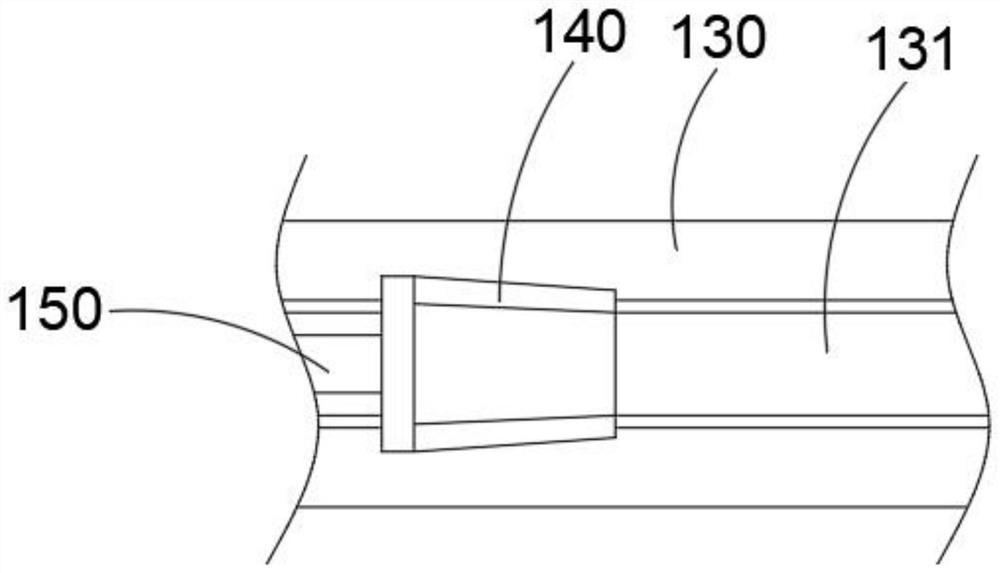
[0052] combine figure 2 As shown, on the basis of the first embodiment, the middle part of the conveying table 130 is provided with a conveying trough 131 for limiting the plastic bottle, and the conveying trough 131 makes the movement of the plastic bottle on the conveying table 130 more stable, preventing the plastic bottle from Slide to the side, and the conveying groove 131 can be set as an arc shape similar to the external structure of the plastic bottle, or can be set as a straight face shape or a combination of the two shapes, and it only needs to have a reasonable limit effect on the plastic bottle, so that The reliability and feasibility of the device are improved.

[0053] On the other hand, the bottom of casing 110 is provided with the collection box 111 that is positioned at the cleaning tank 510 and the lid drop opening 660 below, and the front of casing 110 is provided with the switch door 112 that is positioned at collection box 111 side, can be arranged by col...

Embodiment 3

[0056] combine Figure 7 As shown, on the basis of Embodiment 1, the bottom surface of the capping plate 640 is inclined to the movement direction of the plastic bottle, and the bottom surface of the bottle pressing plate 620 is provided with a pressing thorn 621, through the capping plate 640 with an inclined bottom surface, the bottom surface of the capping plate 640 is inclined. When the plate 640 squeezes the bottle cap, it can apply a tilting force to the bottle cap, and the inclined surface is located above the cap drop opening 660, which greatly facilitates the bottle cap falling into the inside of the cap drop opening 660, making the bottle cap easier to fall off. The bottom surface of the capping plate 640 is provided with anti-slip lines, which can prevent the capping plate 640 from slipping off when squeezing the bottle cap, ensuring the stability and accuracy when squeezing the bottle cap, and the pressing thorns 621 can press the plastic bottle. Prevent the plasti...


PUM


Abstract

The invention belongs to the technical field of environment-friendly equipment, and particularly relates to environment-friendly bottle body recycling equipment. The environment-friendly bottle body recycling equipment comprises a material conveying mechanism, a blanching mechanism, a fixed conveying mechanism, a crushing mechanism, a cleaning mechanism and a cover removing mechanism, wherein the material conveying mechanism comprises a box body used for operation protection, a feeding hopper installed on the box body and used for discharging, a material conveying table arranged on the box body and used for conveying materials, a push plate located on the material conveying table and used for pushing the materials, and a first electric push rod connected with the push plate and used for driving the push plate to operate. According to environment-friendly bottle body recycling equipment, a packaging tape passing through a plastic bottle can be heated to be in a contraction state through the blanching mechanism, the strip-shaped packaging tape is more convenient to remove, chippings are not prone to being generated when the packaging tape is broken, glue at the gluing position is melted, the subsequent removing procedure is more convenient, it is guaranteed that no residue exists after the packaging tape is removed, and the normal state of the plastic bottle cannot be influenced by the heating temperature of the packaging belt, so that the pretreatment is relatively reasonable.

Description

technical field [0001] The invention relates to the technical field of environmental protection equipment, in particular to environmental protection type bottle recycling equipment. Background technique [0002] Plastic bottles are mainly made of materials such as polyethylene or polypropylene with the addition of various organic solvents. Polyester (PET), polyethylene (PE) and polypropylene (PP) are widely used as raw materials for plastic bottles. After adding corresponding organic solvents, after high temperature heating, they are blown, extruded, or injection molded through plastic molds. Plastic containers are characterized by unbreakable, low cost, high transparency, and food-grade raw materials. With the increasing use of plastic bottles, the recycling of plastic bottles has become a complete industrial chain. [0003] In the recycling process of existing plastic bottles, the packaging tape on the plastic bottle is generally broken and separated after the sorting is ...

Claims


Application Information

Patent Timeline
Patent Type & Authority Applications(China)
IPC IPC(8): B29B17/00B09B3/00
CPCB29B17/00Y02W30/62Y02W30/82
Inventor 徐帅帅
Owner 徐州虹源环保科技有限公司
Learn More