Car washing robot
A robot and car washing technology, applied in the field of car washing robots, can solve the problems of poor car washing cleanliness, time-consuming and labor-intensive manual car washing, etc.
- Summary
- Abstract
- Description
- Claims
- Application Information
AI Technical Summary
Problems solved by technology
Method used
Image

Examples
Embodiment 1
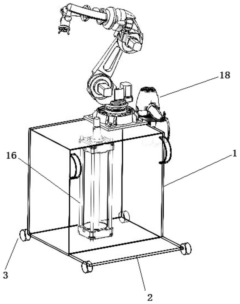
[0037] A car washing robot, comprising a walking base, a water tank 1 assembled on the walking base, a car washing pipeline for water supply, a mechanical arm assembled on the top of the water tank to adjust the water outlet position of the car washing pipeline, and a control system ;
[0038] The walking base includes a base plate 2 and a follower wheel and two walking wheels 3 assembled below the base plate, each of which is driven by a servo motor;
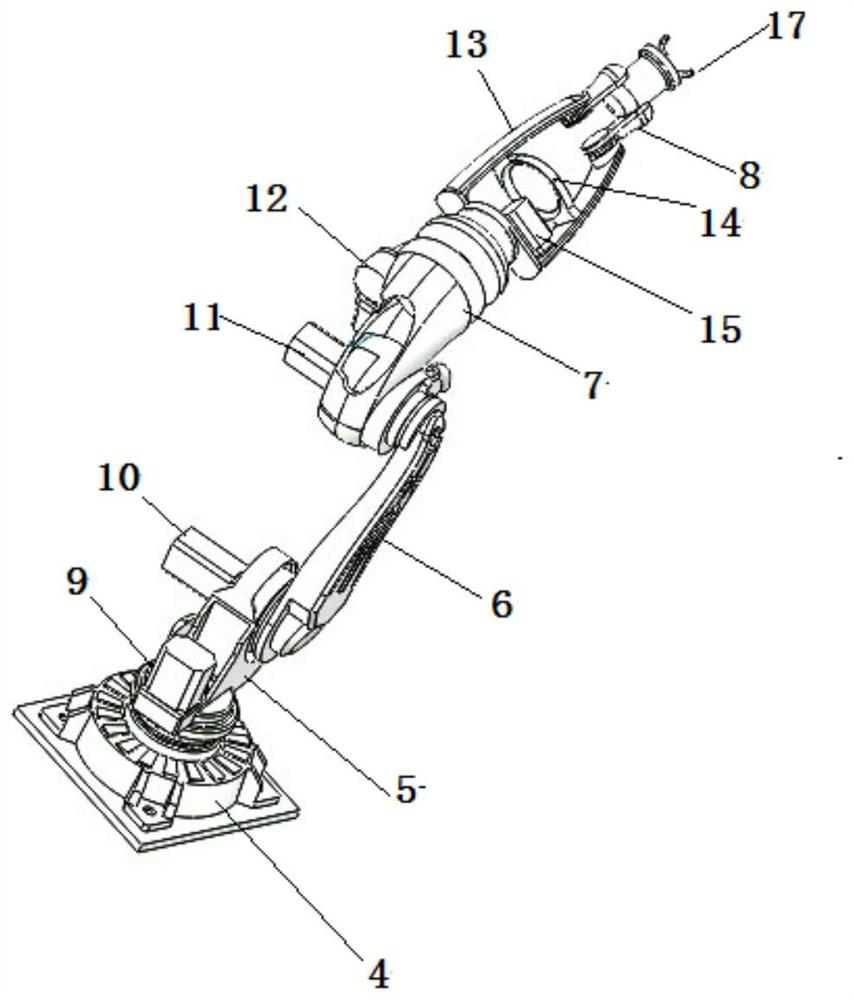
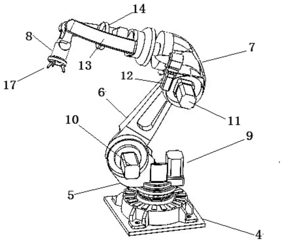
[0039] The mechanical arm includes a first joint, a big arm 5, a second joint, a small arm 6, a third joint, a wrist 7, a fourth joint, a connecting rod, a fifth joint and a finger 8 connected in sequence;
[0040] The first joint includes a rotating seat 4 fixed on the water tank 1, a first rotating pair assembled in the rotating seat 4, and a first driving motor 9 for driving the first rotating pair. The bottom of the arm 5 is driven by the first rotation pair to rotate on the XY plane;
[0041] The second joint includes a ...
Embodiment 2
[0051] This embodiment further illustrates the rotating arm.
[0052] The rotary pair in this embodiment can all adopt the gear pair. The second joint housing is fixed on the big arm 5, the third joint housing and the fourth joint housing are respectively fixed on both ends of the wrist, and the fifth joint housing is fixed on the Connect the end of the arm 13.
[0053] More preferably, the forearm 6 is a straight arm, and the wrist is an arc structure with a radian of 90-120°. Straight arms and curved wrists combine for more room to move.
[0054] More preferably, the rotation angle of the big arm 5 is 270°, the rotation angle of the small arm 6, wrist 7, connecting rod, fifth joint and finger 8 is greater than 90°, and the material is high-strength aluminum alloy . The water tank 1 stores 40L of water at one time, meeting the water storage requirement. The extension of the mechanical arm is greater than 3 meters, and the rotation angle of the fuselage is greater than 27...
Embodiment 3
[0060] In order to dry in time after the car washing is completed, the car washing robot is also equipped with a blowing system. Realize the drying function.
[0061] Preferably, the blowing system includes a blower 18 and a bracket fixed on the water tank for placing the blower. When in use, manually remove the hair dryer, and then operate the hair dryer to dry the car. Manually control the blowing direction and start and stop.
[0062] More preferably, the blowing system includes a hot air blower, an air supply pipeline connected with the hot air blower, and an air outlet connected to the end of the air supply pipeline, and the end of the air supply pipeline passes through Pass through the limiting ring 14 and the air outlet is fixed on the finger 8 . The air outlet can adopt bell mouth to expand the drying area. In this way, by controlling the mechanical arm and controlling the position of the air outlet, different areas of the car can be dried. Automatically control t...
PUM
| Property | Measurement | Unit |
|---|---|---|
| Radian | aaaaa | aaaaa |
| Rotation angle | aaaaa | aaaaa |
| Rotation angle | aaaaa | aaaaa |
Abstract
Description
Claims
Application Information
 - R&D
- Intellectual Property
- Life Sciences
- Materials
- Tech Scout
- Unparalleled Data Quality
- Higher Quality Content
- 60% Fewer Hallucinations
Browse by: Latest US Patents, China's latest patents, Technical Efficacy Thesaurus, Application Domain, Technology Topic, Popular Technical Reports.
© 2025 PatSnap. All rights reserved.Legal|Privacy policy|Modern Slavery Act Transparency Statement|Sitemap|About US| Contact US: help@patsnap.com