
Distributed type coal mine gas pressure measuring system

A technology of coal mine gas and measurement system, which is applied in the field of coal mine equipment, can solve the problems of reduced utilization rate and increased cost of pressure measurement equipment, and achieve the effect of improving utilization rate

Inactive Publication Date: 2021-09-07
HENAN INST OF ENG
View PDF0 Cites 2 Cited by
  • Summary
  • Abstract
  • Description
  • Claims
  • Application Information

AI Technical Summary

Problems solved by technology

In the process of mining coal in shafts, accurate measurement of gas pressure is the key to safe, efficient and rapid coal removal. Most of the current gas pressure measuring devices use piezometric tubes, grouting tubes and baffle plates in the boreholes of the coal seams to be tested. Cement mortar is injected into the borehole through the grouting pipe. After the pressure is measured, the borehole is usually further blocked, so that the relevant equipment is blocked in the borehole, which reduces the utilization rate of the pressure measuring equipment and increases the cost.

Method used


Image

  • Distributed type coal mine gas pressure measuring system
  • Distributed type coal mine gas pressure measuring system
  • Distributed type coal mine gas pressure measuring system

Examples


Embodiment 1

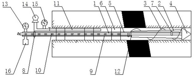
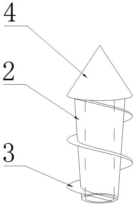
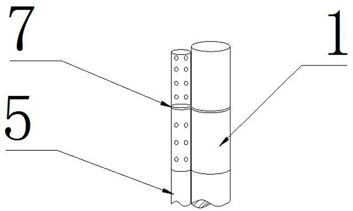
[0019] like Figure 1-5 A distributed coal mine gas pressure measuring system, including the pressure tube 5, drill pipe 1, the air tube 9, and the first water pipe 10, and the drill pipe 1 is provided with a double-shaft member 7, and a spiral is provided on the drill pipe 1. The rod 2 is provided with a drill bit 4 that is fixedly coupled to the spiral rod 2. The drill rod 1 is connected to the pressure pipe 5 through the double-shaft 7, and the drill pipe is provided with a first water pipe 10. There is a rubber water bag 6 in communication with the first water pipe 10.

[0020] A rubber water bladder 6 is provided with at least 1 in which the drill pipe is communicated with the first water pipe 10 is provided with a valve, and the drill rod 1 is divided into a solid structure in the spiral rod 2, and the drill pipe 1 is provided with The pressure tube 5 is connected to the three-axis 8 connected to the air tube 9 axis.

[0021] The spiral rod 2 is provided with a hollow structu...

Embodiment 2

[0025] A distributed coal mine gas pressure measuring system, which is compared with Example 1, the rubber water bag 6 is three, and the drilling hole is sealed by two aqueous layers, enhancing the sealing property, and the spiral rod 2 is installed with a grille. The grille can block a portion of the dust into the spiral rod 2 inside the retention of the pressure tube 5 is not blocked, and the water between the rubber water bags 6 is extracted after the pressure is completed, and then the water in the rubber water bag 6 is then discharged, and then drill The rod 1 is taken out from the drilling, and the hole is performed by the sealing device, and then the interior of the spiral rod 2 is cleaned by the air tube 9 or the pressure tube 5 to prevent the pressure pipe 5 from blocking.


PUM


Abstract

The invention relates to a distributed type coal mine gas pressure measuring system. The distributed type coal mine gas pressure measuring system comprises a pressure measuring pipe, a drill rod, an air pipe and a first water pipe, a double-shaft device is arranged on the drill rod, a screw rod is arranged on the drill rod, a drill bit fixedly connected with the screw rod is arranged at one end of the drill rod, the drill rod is connected with the pressure measuring pipe and the air pipe through the double-shaft device, the first water pipe is arranged in the drill rod, and rubber water bags communicating with the first water pipe are arranged on the drill rod. According to the distributed type coal mine gas pressure measuring system, the pressure measuring pipe is arranged in the screw rod, so that the phenomenon that the pressure measuring pipe is blocked due to falling of a coal seam during drilling is avoided; and meanwhile, the screw rod rotates along with the drill rod to output falling coal briquettes outwards, then the coal briquettes are blown out of a drill hole through an air nozzle, the plurality of rubber water bags are filled with water, so that the size is increased, the friction force between the water bags and the drill hole is increased, water is injected among the water bags for water sealing, the repeated utilization rate of equipment is increased, and the cost is reduced.

Description

Technical field [0001] The present invention belongs to the technical field of coal mine equipment, in particular, to a distributed coal mine gas pressure measurement system. Background technique [0002] Gas pressure in coal seam under coal mine is one of the most important indicators of gas foundation parameters, directly related to the gas governance program. During the unveiling of well alley, accurately determine that gas pressure is more secure, efficient, rapidly reveals the key. The current gas pressure sensitizer is mostly used to measure the pressure tube, grouting tube and retaining plate in the drilling of the coal seam. The cement mortar is injected into the inside in the bore, and the drilling is usually further blocked after the pressure is measured, so that the relevant equipment is blocked in the drilling, so that the usage rate of the shifting device is lowered, increasing cost. Inventive content [0003] It is an object of the present invention to solve the ma...

Claims


Application Information

Patent Timeline
Patent Type & Authority Applications(China)
IPC IPC(8): E21B47/06E21B47/01E21B17/22E21B21/16E21B33/126
CPCE21B47/06E21B47/01E21B17/22E21B21/16E21B33/1208E21B33/126
Inventor 于红张帆陶云奇吴金刚周银波郭军杰荆永滨
Owner HENAN INST OF ENG
Learn More