
Distributed antenna layout optimization design method and system

A distributed antenna and layout optimization technology, applied in the field of antenna layout design, can solve problems such as main lobe interference

Active Publication Date: 2021-09-07
CHINA ELECTRONIC TECH GRP CORP NO 38 RES INST
View PDF8 Cites 0 Cited by
  • Summary
  • Abstract
  • Description
  • Claims
  • Application Information

AI Technical Summary

Problems solved by technology

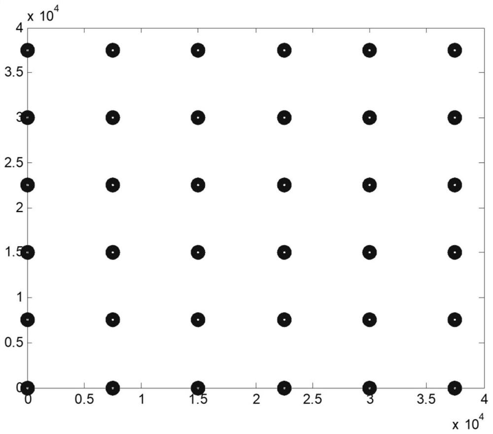
Taking 36 reflector array elements as an example for simulation calculation, under the rectangular grid arrangement, the gain difference between the grating lobe and the main lobe is about 1dB. If the interference of the adjacent spacecraft enters through the grating lobe, it is easy to cause interference to the main lobe

Method used


Image

  • Distributed antenna layout optimization design method and system
  • Distributed antenna layout optimization design method and system
  • Distributed antenna layout optimization design method and system

Examples


Embodiment Construction

[0043] The embodiments of the present invention are described in detail below. This embodiment is implemented on the premise of the technical solution of the present invention, and detailed implementation methods and specific operating procedures are provided, but the protection scope of the present invention is not limited to the following implementation example.

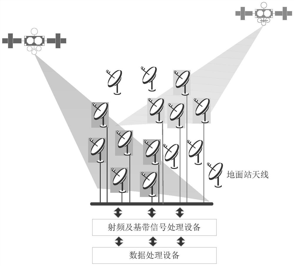
[0044] Such as figure 1 As shown, it is a schematic diagram of the distributed small-aperture ground station antenna layout scene in this embodiment, and the position coordinates of the following particle optimizations are the positions of each antenna.

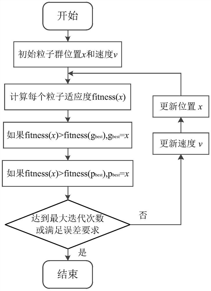
[0045] Such as figure 2 As shown, this embodiment provides a technical solution: a distributed antenna layout optimization design method, including the following steps:

[0046] (1) Define the solution space: the first step of executing the particle swarm optimization algorithm is to select the parameters x to be optimized and give them a suitable value range. ...


PUM


Abstract

The invention discloses a distributed antenna layout optimization design method and system, and belongs to the technical field of antenna layout design, and the method comprises the following steps: S1, defining a solution space; S2, defining a fitness function; S3, initializing the random position and speed of a particle swarm; S4, gradually searching an optimum in the solution space; S5, updating the particle speed; S6, updating particle positions. By applying the particle swarm optimization, under the condition that the minimum unit spacing requirement is met, an array coordinate position serves as a variable, array arrangement is optimized, a reasonable and corresponding fitness function is designed, the gain difference between a grating lobe and a main lobe can be remarkably reduced, and therefore the effects of restraining the grating lobe and improving the anti-interference capacity of the system are achieved, and the method is worthy of being used and popularized.

Description

technical field [0001] The invention relates to the technical field of antenna layout design, in particular to a distributed antenna layout optimization design method and system. Background technique [0002] The new-generation ground station system uses a large number of small-caliber antennas for distributed array formation. If many reflector antennas are arranged in a regular regular grid, such as a rectangular grid or a triangular grid, the distance between the array elements is far beyond If the wavelength of the working frequency band is exceeded, multiple grating lobes will be generated near the main lobe, and the gain value is close to the main lobe. Taking 36 reflector array elements as an example to carry out simulation calculations, under the rectangular grid arrangement, the gain difference between the grating lobe and the main lobe is about 1dB. If the interference of adjacent spacecraft enters through the grating lobe, it is easy to cause interference to the ma...

Claims


Application Information

Patent Timeline
IPC IPC(8): G06F30/18G06F30/25G06N3/00G06F111/08
CPCG06F30/18G06F30/25G06N3/006G06F2111/08
Inventor 王烁吴瑞荣任伟龙赵忠超姚艳军章明明赵宇峰王昕裴恒魏驷张志成
Owner CHINA ELECTRONIC TECH GRP CORP NO 38 RES INST
Learn More