
Electrolytic machining device for synchronously realizing microstructures on inner surface of barrel workpiece and outer surface of cylindrical workpiece

A technology for a cylindrical workpiece and a processing device, which is applied in the field of electrolytic machining devices, can solve the problems of cumbersome film-making process for photolithography, difficult to guarantee the quality of the film, and increase of the process cost.

Active Publication Date: 2021-09-10
HENAN POLYTECHNIC UNIV +1
View PDF10 Cites 2 Cited by
  • Summary
  • Abstract
  • Description
  • Claims
  • Application Information

AI Technical Summary

Problems solved by technology

This method uses photolithography to pattern the outer surface of the cylinder or attach a flexible mask to the processing surface, and uses the sleeve as the cathode of the tool for electrolytic processing to prepare the microstructure of the outer surface of the cylinder, but it has disadvantages: The film engraving process is cumbersome, the process cost is high, and the quality of the film is difficult to guarantee
For rotary parts, the biggest difficulty in surface microstructure processing is the preparation of high-quality and high-precision masks on curved surfaces, especially the electrolytic processing of anode masks, which increases the process cost.

Method used


Image

  • Electrolytic machining device for synchronously realizing microstructures on inner surface of barrel workpiece and outer surface of cylindrical workpiece
  • Electrolytic machining device for synchronously realizing microstructures on inner surface of barrel workpiece and outer surface of cylindrical workpiece

Examples


Embodiment Construction

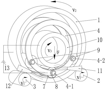
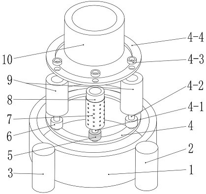
[0026] Taking the simultaneous processing of two cylindrical rotary workpieces as an example, the embodiments of the present invention will be further described in conjunction with the accompanying drawings.

[0027] Such as figure 1 with figure 2 As shown, an electrolytic machining device for synchronously realizing the microstructure of the inner surface of a cylindrical workpiece and the outer surface of a cylindrical workpiece includes a cylindrical workpiece I1 with an inner diameter of 80 mm, a cylindrical workpiece II10 with an outer diameter of 40 mm, and a diameter of 15mm cylindrical roller cathode 8, cathode mask 7 closely attached to the outer surface of roller cathode 8, auxiliary roller 9 with a diameter of 17.5mm, cage assembly 4 for clamping roller cathode 8 and auxiliary roller 9, conductive Bearing 5, electrical insulation bearing 6, idler roller I2, idler roller II3, conductive shaft 4-1, nozzle I11, nozzle II12 and power supply 13; workpiece I1, workpiece...


PUM


Abstract

The invention discloses an electrolytic machining device for synchronously realizing microstructures on the inner surface of a barrel workpiece and the outer surface of a cylindrical workpiece, and belongs to the field of electrolytic machining. The electrolytic machining device comprises the barrel workpiece I, the workpiece II with a cylindrical outer surface, a roller cathode, a cathode mask, an auxiliary roller, a retainer assembly, a conductive bearing, an electric insulation bearing, a carrier roller I, a carrier roller II, a conductive shaft, an electrolyte nozzle and a power supply. The workpiece I is placed on the carrier roller I and the carrier roller II, the workpiece II is arranged in the workpiece I and is tightly pressed on the roller cathode and the auxiliary roller under the action of external force, the carrier rollers drive the workpiece I to rotate at a constant speed, and the cathode mask and the auxiliary roller are in tight contact with the workpiece I and the workpiece II all the time, so that the surfaces of the workpieces are continuously machined while continuous power is transmitted. By means of the electrolytic machining device, one-time whole-circle machining of the microstructures on the inner surface of the barrel workpiece and the outer surface of the cylindrical workpiece can be synchronously achieved, the machining process is stable and efficient, the machining quality is good, and the cost is low.

Description

technical field [0001] The invention relates to the technical field of electrolytic machining, in particular to an electrolytic machining device for synchronously realizing the microstructure of the inner surface of a cylindrical workpiece and the outer surface of a cylindrical workpiece. Background technique [0002] Transmission products are commonly used in various rotating connections. Plain bearings are one of the preferred rotating connections. Research and application have shown that adding an optimized microstructure on the surface of the rotating assembly can effectively improve the friction characteristics and reduce the friction coefficient, thereby reducing wear and increasing service life. [0003] At present, the main methods for preparing metal surface microstructures are: high-energy beam (such as laser beam, electron beam, etc.) processing, micromachining, chemical etching, electrochemical etching, and electrodeposition processing. Among them, mask electro...

Claims


Application Information

Patent Timeline
IPC IPC(8): B23H3/00B23H3/10
CPCB23H3/00B23H3/10
Inventor 明平美张云燕牛屾周涛韩磊张亚楠闫亮郑兴帅李冬冬
Owner HENAN POLYTECHNIC UNIV
Learn More