Force-sensing motion self-following lifting device
A lifting device and induction motion technology, which is applied in hoisting devices, clockwork mechanisms, etc., can solve the problems of inconvenient operation, high cost, and prone to false touches of lifting handrails
- Summary
- Abstract
- Description
- Claims
- Application Information
AI Technical Summary
Problems solved by technology
Method used
Image

Examples
Embodiment 1
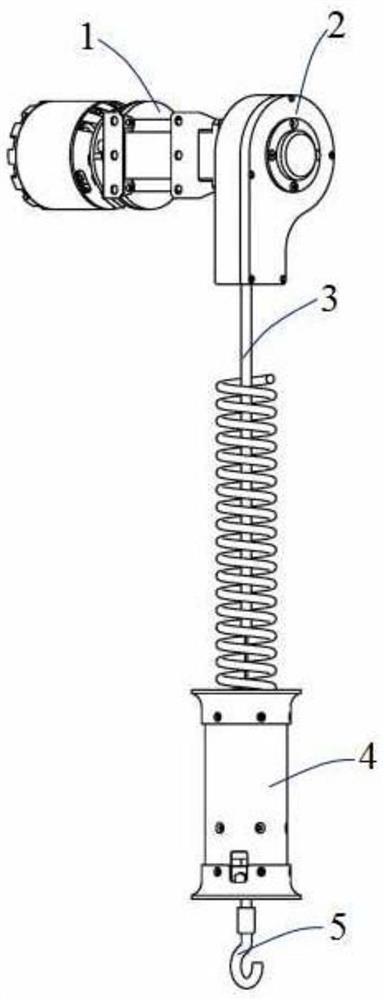
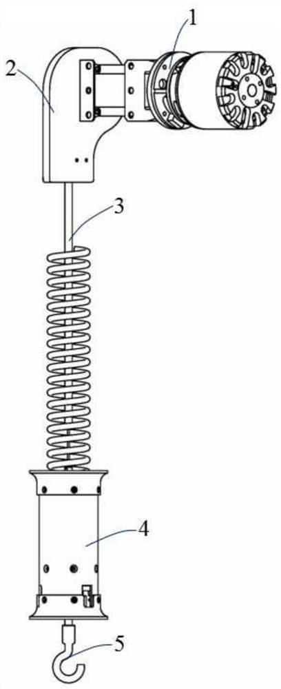
[0056] This embodiment provides a force-sensing motion self-following lifting device, and its structural schematic diagram is as follows figure 1 and figure 2 As shown, it includes a power unit 1, a sheave mechanism 2, a Bowden wire 3, an induction mechanism 4 and a spreader 5 from top to bottom.
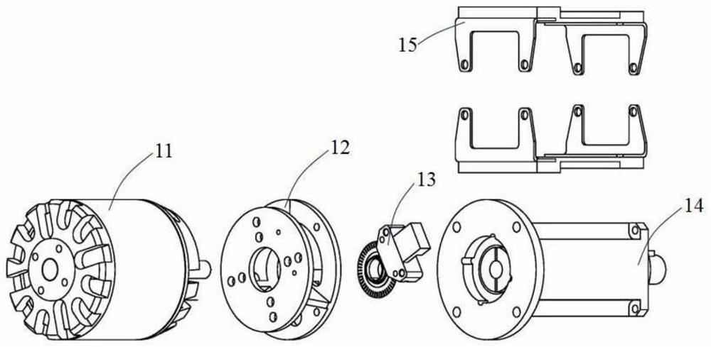
[0057] Such as image 3 As shown, the power unit 1 includes a servo motor 11 , a motor flange 12 , an encoder 13 , a reducer 14 , and a mounting plate 15 . The servo motor 11 is connected to the reducer 14 through the electrode flange 12 , the encoder 13 is installed in the slot hole of the electrode flange 12 , and the mounting plate 15 is installed on the reducer 14 for fixing the power unit 1 .
[0058] Such as Figure 4 As shown, the sheave mechanism 2 includes a first sheave housing 21, a drive shaft 22, a first bearing 23, a first spacer 24, a sheave 25, a Bowden wire limiter 26, a second spacer 27, The second bearing 28 , the damping wheel 29 , the second sheave shell 21...
Embodiment 2
[0061] In the following, some specific actions of a force-sensing motion self-following lifting device will be combined to illustrate the lifting and assisting process of the present invention through the working principle.
[0062] Hook the sling 5 on the heavy object, and the tension sensor 418 can measure the weight of the heavy object. When the operator holds the outer cylinder 42 with his hand and applies a little force upward, the fixed plate 414 will squeeze the spring 412, changing the pressure sensor 415. The pressure value, the control board 44 intelligently recognizes the collected sensor data, calculates the size and direction of the lifting power of the device, drives the servo motor 11, and then drives the sheave 25 to rotate, pulls the inner core 31 of the Bowden wire to transmit the torque to the spreader 5 Assist to achieve the purpose of hoisting heavy objects.
[0063] The present invention mainly has the following technical characteristics:
[0064] The tr...
Embodiment 3
[0070] This embodiment provides a force-sensing motion self-following lifting device, which includes components such as a power unit, a sheave mechanism, a Bowden wire, an induction mechanism, and a spreader from top to bottom; the power unit includes a servo motor, a motor flange, etc. , an encoder, a reducer, and a mounting plate; the sheave mechanism includes a first sheave shell, a drive shaft, a first bearing, a first spacer, a sheave, a Bowden line limiter, a second spacer, a first Two bearings, a damping wheel, a second sheave shell and a sheave end cover; the Bowden wire includes a Bowden wire inner core and a Bowden wire sheath; the induction mechanism includes an upper retaining ring on the outer cylinder, an outer cylinder, and an outer cylinder Lower retaining ring, control board, support rod, cable, lock buckle, upper lock nut, adjustment stud, mounting plate, lower lock nut, spring, spring guide seat, fixed plate, pressure sensor, heart ring, sensor mount , Tensi...
PUM
 Abstract
Description
Claims
Application Information
 - R&D
- Intellectual Property
- Life Sciences
- Materials
- Tech Scout
- Unparalleled Data Quality
- Higher Quality Content
- 60% Fewer Hallucinations
Browse by: Latest US Patents, China's latest patents, Technical Efficacy Thesaurus, Application Domain, Technology Topic, Popular Technical Reports.
© 2025 PatSnap. All rights reserved.Legal|Privacy policy|Modern Slavery Act Transparency Statement|Sitemap|About US| Contact US: help@patsnap.com