
Underwater unmanned self-walking cutter suction device

A self-propelled and cutter suction technology, applied in mechanically driven excavators/dredgers, earth movers/shovels, construction, etc. inequality problem

Active Publication Date: 2021-09-10
SHANGHAI JIAO TONG UNIV
View PDF7 Cites 1 Cited by
  • Summary
  • Abstract
  • Description
  • Claims
  • Application Information

AI Technical Summary

Problems solved by technology

[0003]The current common underwater dredging or mining equipment is mainly equipped with a spiral cutter head that can only pitch up and down, but the existing spiral cutter head has a fixed width. The dredging effect is not good for rough water bottom, and the excavation force is uneven, which is easy to generate yaw moment on the whole machine, making it difficult to control the traveling route of the whole machine; because the dredging actuator can only pitch up and down, it is not flexible enough, and it is difficult to fine-tune the bottom of the water dredging operation
[0004] patent document CN111733915A discloses an assembled electric environment-friendly deep-water dredging ship, comprising: a hull, including a main floating body and a side floating body, and the main floating body is provided with an operating The room and the engine room of the generator set are arranged inside, and the gantry frame is fixedly arranged on the side floating body; the front working mechanism includes a bridge frame, an anchor rod and a bridge frame winch, and the bridge frame is hinged at one end of the hull, and the bridge frame is controlled The bridge winch arranged on the side floating body; the mud cleaning mechanism, including the mud pipe fixed on the bridge, the reamer head installed at the front end of the mud pipe and the mud pump for conveying mud ; and the rear working mechanism, including the positioning pile, the positioning pile hoop for fixing the positioning pile and the piling winch for controlling the lifting of the positioning pile, but the design passes through the hull and the positioning pile, and the dredging flexibility is poor

Method used


Image

  • Underwater unmanned self-walking cutter suction device
  • Underwater unmanned self-walking cutter suction device
  • Underwater unmanned self-walking cutter suction device

Examples


Embodiment Construction

[0075] The present invention will be described in detail below in conjunction with specific embodiments. The following examples will help those skilled in the art to further understand the present invention, but do not limit the present invention in any form. It should be noted that those skilled in the art can make several changes and improvements without departing from the concept of the present invention. These all belong to the protection scope of the present invention.

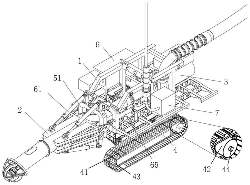
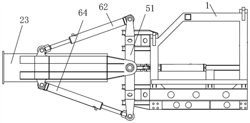
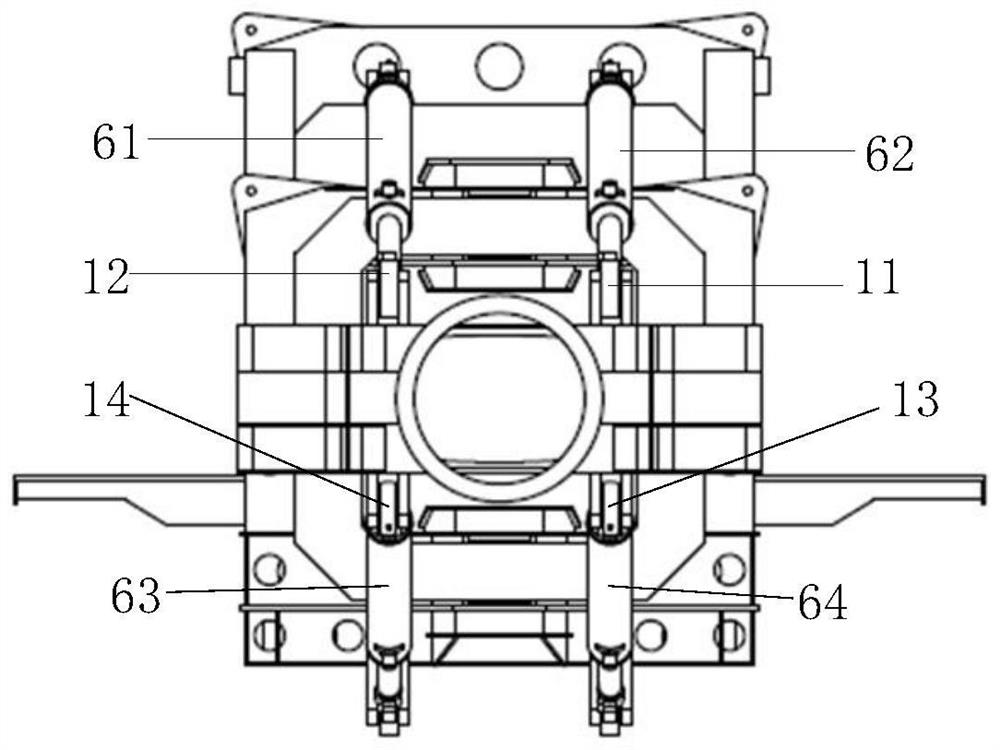
[0076] The invention provides an underwater unmanned self-propelled suction device, such as figure 1 As shown, it includes an excavation system 2, a conveying system 3 and a walking system 4. The excavation system 2 includes a vehicle frame 1, a winch frame 23 and a yaw frame 51, and the winch frame 23 is installed on the yaw frame 51. The digging end on the vehicle frame 1 and on the winch 23 can move relative to the vehicle frame 1 with a rotation trajectory parallel to the first plane and / or a rotati...


PUM


Abstract

The invention provides an underwater unmanned self-walking cutter suction device. The device comprises an excavation system, a conveying system and a walking system, wherein the excavation system comprises a frame, a cutter ladder and a transverse swing frame; the cutter ladder is installed on the frame through the transverse swing frame, the excavation end of the cutter ladder can move relative to the frame in a rotating track parallel to a first plane and / or a rotating track parallel to a second plane, and the first plane is perpendicular to the second plane; the conveying system is installed on the frame, one end of the conveying system is connected with the excavation system, and the other end of the conveying system extends to the outside of the frame; and the walking system is installed at the bottom of the frame and used for driving the excavation system to walk. By adopting the cross axle frame structure in which the transverse swing frame, the cutter ladder and a frame body are hinged, the left-right transverse swing and up-down pitching actions of the cutter ladder are realized, so that the cutter suction machine can realize flexible operation in an underwater complex area.

Description

technical field [0001] The invention relates to the technical field of dredging equipment, in particular to an underwater unmanned self-propelled suction device. Background technique [0002] At present, most of the existing reservoirs and lakes around the world have experienced serious sedimentation after years of operation, which greatly reduces the effective storage capacity and endangers the safety of reservoirs and dams. At the same time, harmful pollutants contained in the sediment are also causing The internal source of water pollution needs to be dredged in time. [0003] At present, the common underwater dredging or mining equipment is mainly equipped with a spiral cutter head that can only be pitched up and down. However, the existing spiral cutter head has a fixed width, which is not effective for dredging rough underwater, and the excavation force is uneven. It is easy to generate a yaw moment to the whole machine, which makes it difficult to control the traveli...

Claims


Application Information

Patent Timeline
Patent Type & Authority Applications(China)
IPC IPC(8): E02F3/88E02F5/28
CPCE02F3/8866E02F5/28
Inventor 何炎平刘炜煌赵永生张戟郑金龙李铭志周丙浩黄超谷孝利刘亚东陈哲
Owner SHANGHAI JIAO TONG UNIV
Learn More