Light steel concrete prestress combined type wind power tower drum section and wind power tower thereof

A wind power tower and prestressing technology, applied in the field of wind power tower structure, can solve the problems of inconvenient assembly, inability to design the tower's wind resistance, earthquake resistance, shear resistance, and transportation inconvenience.

Active Publication Date: 2021-09-10
CHONGQING UNIV
View PDF19 Cites 1 Cited by
  • Summary
  • Abstract
  • Description
  • Claims
  • Application Information

AI Technical Summary

Problems solved by technology

[0004] Aiming at the deficiencies of the prior art, the present invention provides a light-steel concrete prestressed combined wind power tower section and its wind power tower, which has the advantages of being able to assemble and pour the tower section on site, and solves the problem of towers with fix

Method used


Image

  • Light steel concrete prestress combined type wind power tower drum section and wind power tower thereof
  • Light steel concrete prestress combined type wind power tower drum section and wind power tower thereof
  • Light steel concrete prestress combined type wind power tower drum section and wind power tower thereof

Examples


Embodiment 1

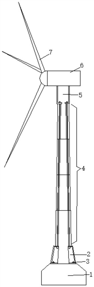
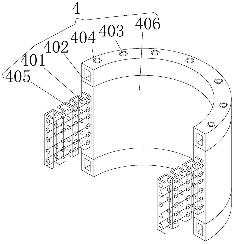
[0037] Such as Figure 1~4 A light-steel concrete prestressed combined wind power tower section is shown, including several arc-shaped prefabricated tower sections spliced ​​with each other. The end faces of the prefabricated tower sections can be semi-circular or 1 / 3 circular. Or 1 / 4 ring, the present embodiment takes the semi-circular ring as an example, each piece of prefabricated tower section segment 4 all includes arc-shaped plates and light steel pipes 402 fixedly installed on the upper and lower sides of the arc-shaped plates by welding, light steel The end faces of the steel pipes 402 are square, and the light-steel steel pipes 402 arc-shaped end faces are provided with stress holes 404 that are convenient for piercing the prestressed tendons 403. The steel mesh 401 and the concrete 406 poured on the outside of the steel mesh 401, the corrugated steel plate 405 is provided with through holes to facilitate mutual communication between the two sides of the corrugated st...

Embodiment 2

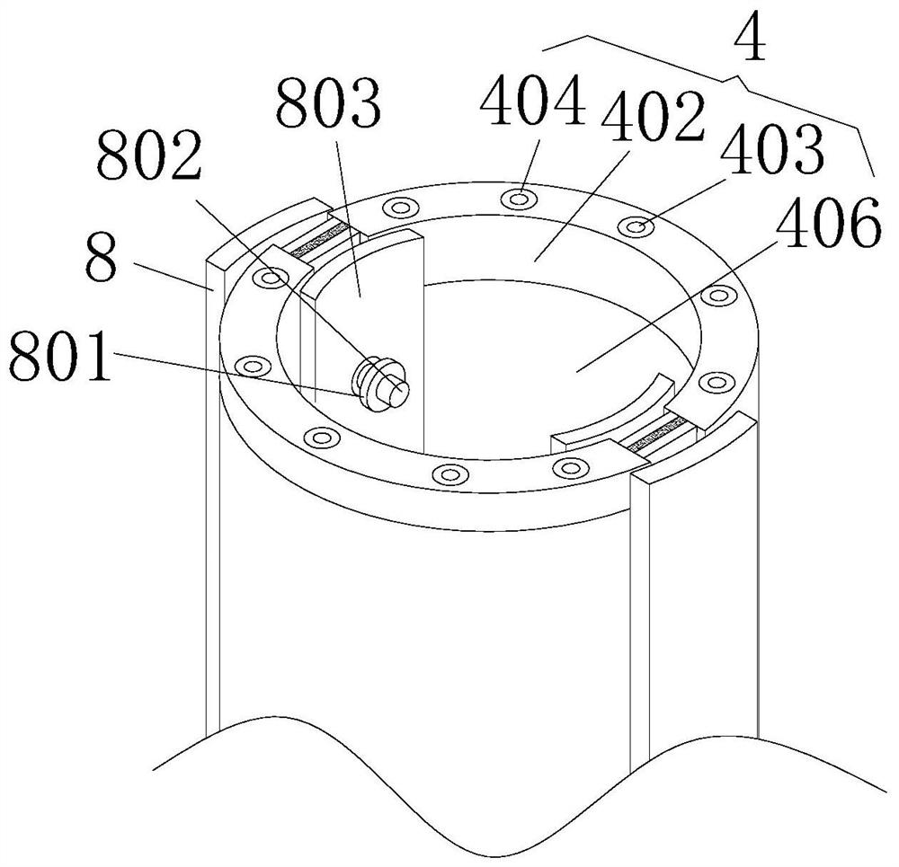
[0047] Such as Figure 1-7 The difference between Embodiment 3 and Embodiment 1 of a light steel concrete prestressed combined wind power tower section shown is that the side of the outer steel plate formwork 8 and the inner steel formwork 802 facing the prefabricated tower section segment 4 are all fixedly connected. There is a fixed rod 804, and the light steel pipe 402 is provided with a fixed hole that is compatible with the fixed rod 804. The outer surface of the fixed rod 804 is provided with a built-in groove 806, and the internal rotation of the built-in groove 806 is connected with a clamping plate 805, and the built-in groove 806 A spring 807 is fixedly connected to the inside of the spring 807, and one end of the spring 807 that is not in contact with the built-in groove 806 is fixedly connected to the clamping plate 805, and the clamping plate 805 is set obliquely. The fixed rod 804 is inserted into the fixed hole provided by the light steel pipe 402. At this time,...

Embodiment 3

[0053] Such as Figure 8 The difference between Embodiment 3 and Embodiment 1 of a light-steel concrete prestressed combined wind power tower section shown is that the end face of the prefabricated tower section is 1 / 4 ring. Adjacent prefabricated tower sections are overlapped and fixedly connected through the cooperation of outer steel formwork, inner steel formwork, nuts and screws. The assembly method of the light steel concrete prestressed combined wind power tower section is the same as that of the first embodiment.


PUM


Abstract

The invention relates to a light steel concrete prestress combined type wind power tower drum section and a wind power tower thereof. The light steel concrete prestress combined type wind power tower drum section comprises a plurality of mutually spliced arc-shaped prefabricated tower drum section fragments, and each prefabricated tower drum section fragment comprises an arc-shaped plate and light steel pipes fixedly mounted on the upper side and the lower side of the arc-shaped plate; stress holes facilitating penetration of prestressed tendons are arranged on the arc-shaped end faces of the light steel pipes; each arc-shaped plate comprises a curved corrugated steel plate, reinforcing meshes arranged on the two sides of the corrugated steel plate and concrete poured on the outer sides of the reinforcing meshes, and through holes facilitating mutual circulation of the concrete on the two sides of the corrugated steel plate are arranged on the corrugated steel plate; and fastening devices are fixedly installed between the adjacent prefabricated tower tube section fragments. The prestress combined type wind power tower tube section has the advantage that the tower tube section can be assembled and poured on site.

Description

technical field [0001] The present invention relates to the technical field of wind power tower structure, and relates to a light steel concrete prestressed combined wind power tower section and its wind power tower, in particular to a corrugated steel bone type light steel concrete prestressed combined wind power tower section and its wind power tower. Background technique [0002] my country's social development has been rapid in recent decades, and it has now become the second largest country in the world in terms of GDP. However, behind the rapid development there are also serious environmental pollution problems, such as the greenhouse effect, smog, acid rain and so on. Today, the international situation is fiercely competitive, and global fossil energy storage can no longer meet the fierce development needs of various countries. At this juncture of the era, it is imperative to develop and utilize clean energy. In recent years, wind energy has been vigorously develope...

Claims


Application Information

Patent Timeline
IPC IPC(8): F03D13/20F03D80/00
CPCF03D13/20F03D80/00Y02E10/728Y02E10/72
Inventor 白久林李晨辉王宇航周绪红
Owner CHONGQING UNIV
Why Eureka
Try Eureka