
Backflow type waste gas incinerator and environment-friendly waste gas treatment method thereof

A technology of incinerator and waste gas, which is applied in the field of backflow waste gas incinerator and its environmental protection treatment of waste gas, and can solve the problems such as the inability to achieve zero discharge of waste gas

Pending Publication Date: 2021-09-10
CHUZHOU JINQIAO TEXAS NEW MATERIALS CO LTD
View PDF0 Cites 0 Cited by
  • Summary
  • Abstract
  • Description
  • Claims
  • Application Information

AI Technical Summary

Problems solved by technology

[0003] Regenerative combustion (RTO) incinerators and catalytic combustion (CO) incinerators in the prior art all adopt the reversing heat storage method, and part of the unburned waste gas is directly discharged and incinerated along with the reverse air flow when the heat storage is reversing. The furnace is discharged into the atmosphere. Although the waste gas treatment meets the national standards, it cannot achieve zero discharge of waste gas

Method used


Image

  • Backflow type waste gas incinerator and environment-friendly waste gas treatment method thereof
  • Backflow type waste gas incinerator and environment-friendly waste gas treatment method thereof
  • Backflow type waste gas incinerator and environment-friendly waste gas treatment method thereof

Examples


Embodiment 1

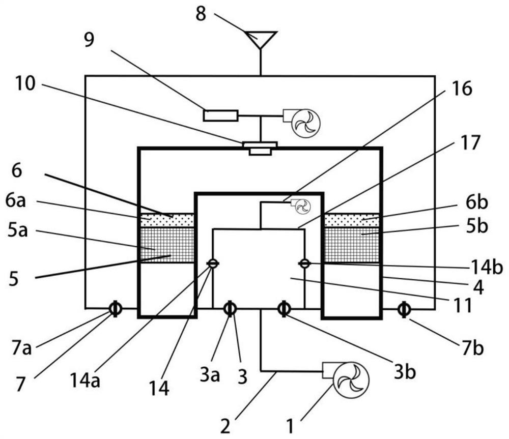
[0033] refer to figure 1 , a backflow type waste gas incinerator, the incinerator is provided with a waste gas inlet pipe 2, a clean air discharge port 8, a U-shaped heating chamber 4 is arranged in the incinerator, the U-shaped heating chamber 4 is connected inside, and a group of The heat storage layer 5 is provided with a burner 10 on the top of the U-shaped heating chamber 4, and the burner 10 is connected with the natural gas pipeline 9, and the waste gas inlet pipe 2 is respectively connected to one side of the two ends of the U-shaped heating chamber 4, and a Intake valve 3, the other side of the two ends of the U-shaped heating chamber 4 are connected to the clean air discharge port 8 through pipelines, and an outlet valve 7 is provided at the connection of both ends, and the inlet valves 3 at different ends of the U-shaped heating chamber 4 are opened during use and air outlet valve 7, so that the exhaust gas can enter any end of the U-shaped heating chamber 4 from th...

Embodiment 2

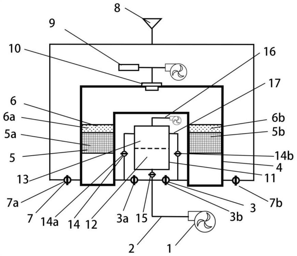
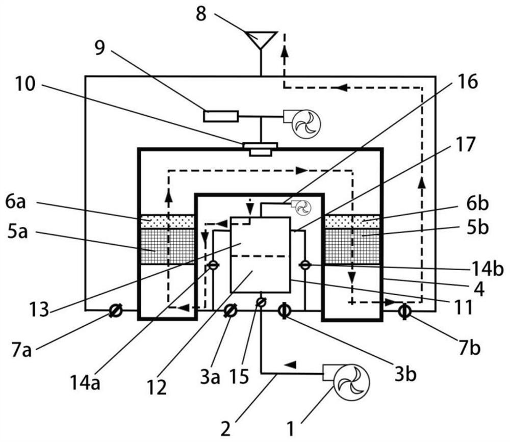
[0043] refer to Figure 2-6 , a backflow type waste gas incinerator, the incinerator is provided with a waste gas inlet pipe 2, a clean air discharge port 8, a U-shaped heating chamber 4 is arranged in the incinerator, the U-shaped heating chamber 4 is connected inside, and a group of The heat storage layer 5 is provided with a burner 10 on the top of the U-shaped heating chamber 4, and the burner 10 is connected with the natural gas pipeline 9, and the waste gas inlet pipe 2 is respectively connected to one side of the two ends of the U-shaped heating chamber 4, and a Intake valve 3, the other side of the two ends of the U-shaped heating chamber 4 are connected to the clean air discharge port 8 through pipelines, and an outlet valve 7 is provided at the connection of both ends, and the inlet valves 3 at different ends of the U-shaped heating chamber 4 are opened during use and air outlet valve 7, so that the exhaust gas can enter any end of the U-shaped heating chamber 4 from...


PUM


Abstract

The invention mainly relates to a backflow type waste gas incinerator and a environment-friendly waste gas treatment method thereof. The backflow type waste gas incinerator is provided with a waste gas inlet pipe and a clean air exhaust port, wherein a U-shaped heating cavity is formed in the incinerator, the interior of the U-shaped heating cavity is through, the two sides of the U-shaped heating cavity are each provided with a heat storage layer, a combustor is arranged at the top of the U-shaped heating cavity and connected with a natural gas pipeline, the waste gas inlet pipe is connected to one side of each of two ends of the U-shaped heating cavity, a gas inlet valve is arranged at the joint of each of the two ends, the other side of each of the two ends of the U-shaped heating cavity is connected to the clean air exhaust port through a pipeline, and a gas outlet valve is arranged at the joint of each of the two ends. According to the backflow type waste gas incinerator, a separator is combined with the clean air inlet pipe and a clean air conveying pipe, waste gas fed by the waste gas inlet pipe is temporarily stored during air exchange, clean air can be input into the U-shaped heating cavity without stopping waste gas conveying, residual waste gas in the U-shaped heating cavity is pushed out, so that the waste gas is completely incinerated and purified, and almost zero emission of VOC waste gas is realized; and the waste gas purification efficiency and the heat energy utilization rate of the incinerator are improved.

Description

technical field [0001] The invention belongs to the technical field of environmental protection equipment, and in particular relates to a backflow type waste gas incinerator and a waste gas environmental protection treatment method thereof. Background technique [0002] Using incineration to treat organic waste gas, highly toxic gas, and malodorous gas is a very effective treatment method. The principle is to use high heat to directly oxidize and decompose harmful substances in the waste gas components, such as oxidizing organic matter into CO2 and H20. In order to save incineration costs, regenerative combustion (RTO) and catalytic combustion (CO) processes are commonly used in daily production. [0003] Regenerative combustion (RTO) incinerators and catalytic combustion (CO) incinerators in the prior art all adopt the reversing heat storage method, and part of the unburned waste gas is directly discharged and incinerated along with the reverse air flow when the heat storag...

Claims


Application Information

Patent Timeline
IPC IPC(8): F23G7/06F23G7/07
CPCF23G7/068F23G7/07Y02A50/20
Inventor 马晓东周伟东李剑
Owner CHUZHOU JINQIAO TEXAS NEW MATERIALS CO LTD
Learn More