
Thermal jet experiment method for shock tunnel

An experimental method, shock tunnel technology, applied in the field of thermal jet flow experiments, can solve problems such as complex structure of the device, difficulty in control, limited range of jet flow parameters, etc.

Active Publication Date: 2021-09-10
INST OF MECHANICS - CHINESE ACAD OF SCI
View PDF6 Cites 9 Cited by
  • Summary
  • Abstract
  • Description
  • Claims
  • Application Information

AI Technical Summary

Problems solved by technology

[0004] The object of the present invention is to provide a kind of thermal jet experiment device for shock wave wind tunnel, to solve the complex structure of the device existing in the thermal jet experiment method in the prior art, limited range of jet flow parameters such as flow rate and temperature and difficult to control technical issues

Method used


Image

  • Thermal jet experiment method for shock tunnel
  • Thermal jet experiment method for shock tunnel
  • Thermal jet experiment method for shock tunnel

Examples


Embodiment 1

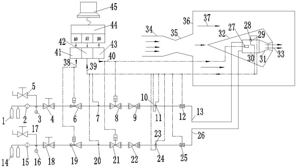
[0175] 1) The aircraft model 32 with the combustion chamber 30 is installed and fixed in the shock tunnel test chamber 36;

[0176] 2) vacuumize the shock wave wind tunnel test chamber 32, and the vacuum degree is 20Pa;

[0177] 3) Connect the hydrogen pipeline 13 and the air pipeline 26 to the air inlet of the combustion chamber 30;

[0178] 4) Manually open the hydrogen cylinder 1 and the air cylinder 14 to ensure that the pressure of the two cylinders is above 10MPa;

[0179] 5) Manually open the main hydrogen shut-off valve 4 and the main air shut-off valve 18;

[0180] 6) input hydrogen pressure reducing valve 6 in computer 45 is 1.3MPa, and the pressure of air pressure reducing valve 19 is 2.0MPa;

[0181] 7) computer control, open the hydrogen electromagnetic shut-off valve 8 and the air electromagnetic shut-off valve 21 at the same time, supply hydrogen and air to the combustion chamber;

[0182] 8) computer control, open the power supply of spark plug 27, spark plu...


PUM


Abstract

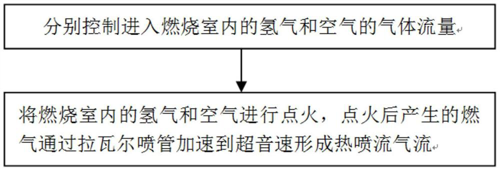
The invention discloses a thermal jet experiment method for a shock tunnel. The thermal jet experiment method comprises the following steps: 1) respectively controlling the gas flow of hydrogen and air entering a combustion chamber; (2) igniting hydrogen and air in the combustion chamber, and accelerating fuel gas generated after ignition to supersonic speed through a Laval nozzle to form hot jet airflow. The hydrogen and the air are respectively conveyed into the combustion chamber through a gas pipeline, and the control of the gas flow comprises the following steps: firstly, regulating the gas pressure in the gas pipeline through a gas pressure reducing valve; and the adjusting the gas flow by a sonic nozzle flowmeter. The thermal jet flow experiment method solves the technical problems that a thermal jet flow experiment method in the prior art is complex in device structure, and jet flow parameters such as flow and temperature are limited in range and difficult to control.

Description

technical field [0001] The invention relates to the field of shock wave wind tunnels, in particular to a thermal jet flow experiment method used in shock wave wind tunnels. Background technique [0002] During the flight of a hypersonic vehicle, the coupling of the internal flow and the external flow of the engine and the jet flow generated to achieve attitude-orbit control will generate strong shock wave / shock wave interference, shock wave / boundary layer interference, and large-scale problems such as separation and reattachment. The unsteady and unsteady flow field will greatly interfere with the aerodynamic force and aerodynamic heat of the aircraft. The aerothermal ground test is mainly carried out in the millisecond shock wave wind tunnel. The generation of a transiently stable thermal jet gas source, timing synchronization within milliseconds, and small-scale models make thermal jet experiments in shock tunnels extremely difficult. [0003] In 2011, Chen Xuedong, Wang...

Claims


Application Information

Patent Timeline
IPC IPC(8): G01M9/02G01M9/06
CPCG01M9/02G01M9/06
Inventor 李龙吴松栗继伟喻江汪球赵伟
Owner INST OF MECHANICS - CHINESE ACAD OF SCI
Learn More