Check patentability & draft patents in minutes with Patsnap Eureka AI!

High-precision optical path debugging device and debugging method thereof

A high-precision, optical path technology, applied in the field of optical optical path, can solve the problems of time-consuming, error, easy attenuation of auxiliary light source intensity, etc.

Active Publication Date: 2021-09-10
福州市纳飞光电科技有限公司
View PDF14 Cites 1 Cited by
  • Summary
  • Abstract
  • Description
  • Claims
  • Application Information

AI Technical Summary

Problems solved by technology

Due to the influence of the accuracy and stability of the measuring instrument equipment, or the possible deviations in the processing and positioning of mechanical parts, the intensity of the auxiliary light source is easy to attenuate, and there are positioning and pointing errors between the auxiliary light source and the actual reference light, etc., Or the addition of auxiliary measuring instruments and equipment will easily lead to the difficulty in debugging the accuracy required by the system, or it will take a long time to correct and debug in order to meet the installation accuracy requirements

Method used


Image

  • High-precision optical path debugging device and debugging method thereof
  • High-precision optical path debugging device and debugging method thereof

Examples


Embodiment Construction

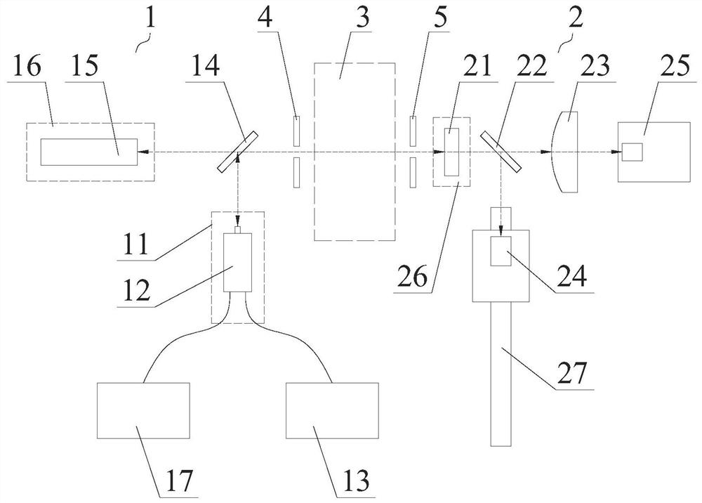
[0026] Below in conjunction with accompanying drawing and specific embodiment the present invention is described in further detail:

[0027] see figure 1 As shown, a high-precision optical optical path debugging device includes a light source module 1 and a receiving module 2. The light source module 1 is used to provide reference light used for debugging and a feedback signal during the debugging process. The receiving module 2 is used for The position and pointing angle of the light beam before and after the test optical path debugging; the light source module 1 includes an adjustment bracket 11, a fiber collimator 12, a reference light source 13 and a first beam splitter 14, and the fiber collimator 12 is installed on the optical five On the dimension adjustment bracket 11, the light output by the reference light source 13 is input into the optical module 3 to be debugged through the fiber collimator 12 and the first beam splitter 14, as a reference light source for optical...


PUM


Abstract

The invention discloses a high-precision optical path debugging device and a debugging method thereof, the high-precision optical path debugging device comprises a light source module and a receiving module, the light source module is used for providing reference light and receiving feedback signals in the debugging process, and the receiving module is used for testing the position and the directional angle of a light beam before and after optical path debugging; the light source module comprises an adjusting support, an optical fiber collimator, a reference light source and a first spectroscope. Light outputted by the reference light source is inputted into the optical module to be debugged through the optical fiber collimator and the first spectroscope. The receiving module comprises a partial reflection beam splitter, a second spectroscope, a coaxial focusing lens, a first light spot machine and a second light spot machine, light outputted by the optical module to be debugged passes through the second spectroscope and then is emitted to the first light spot machine and the coaxial focusing lens, and the light focused after passing through the coaxial focusing lens is inputted into the second light spot machine. According to the invention, the relation between the incident light in front of the optical module and the emergent light behind the optical module can be accurately controlled and monitored, a visual debugging scheme is provided, and the debugging efficiency is high.

Description

technical field [0001] The invention relates to the technical field of optical light paths, in particular to a high-precision optical light path debugging device and a debugging method thereof. Background technique [0002] Optical optical path debugging is the core process in the field of optical machine assembly and laser application. In many optical adjustment applications, such as laser cavity adjustment, fiber coupling, space communication adjustment, etc., such applications often require that the position of the output light of the module coincides with the position of the input light, and the angle between the two needs to meet <10” (0.05mrad), therefore, how to achieve high-precision optical path debugging is a problem that must be considered in the field of optical machine assembly. [0003] Because in the complex optical path system, the optical path reference light is often not visible light, in order to facilitate high-precision adjustment, some auxiliary vis...

Claims


Application Information

Patent Timeline
Patent Type & Authority Applications(China)
IPC IPC(8): G02B27/62
CPCG02B27/62
Inventor 郑广建董灵健
Owner 福州市纳飞光电科技有限公司
Features
  • R&D
  • Intellectual Property
  • Life Sciences
  • Materials
  • Tech Scout
  • Unparalleled Data Quality
  • Higher Quality Content
  • 60% Fewer Hallucinations
Learn More