Check patentability & draft patents in minutes with Patsnap Eureka AI!

Over-temperature protection circuit

A technology for over-temperature protection circuits and resistors, applied in the direction of adjusting electrical variables, control/regulation systems, instruments, etc., can solve problems such as complex implementation

Active Publication Date: 2021-09-10
SHENZHEN LOWPOWER SEMICON CO LTD
View PDF4 Cites 0 Cited by
  • Summary
  • Abstract
  • Description
  • Claims
  • Application Information

AI Technical Summary

Problems solved by technology

The current over-temperature protection circuit is generally realized by using a comparator to compare a reference voltage that does not change with temperature and a voltage with a negative temperature coefficient that decreases with temperature. Among them, the hysteresis function is achieved by changing the reference voltage. Voltage implementation, the implementation is more complicated

Method used


Image

  • Over-temperature protection circuit
  • Over-temperature protection circuit
  • Over-temperature protection circuit

Examples


Embodiment Construction

[0023] The present invention will be described in detail below in conjunction with the accompanying drawings and specific embodiments.

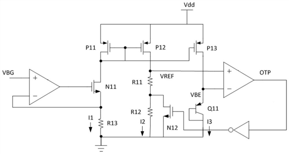
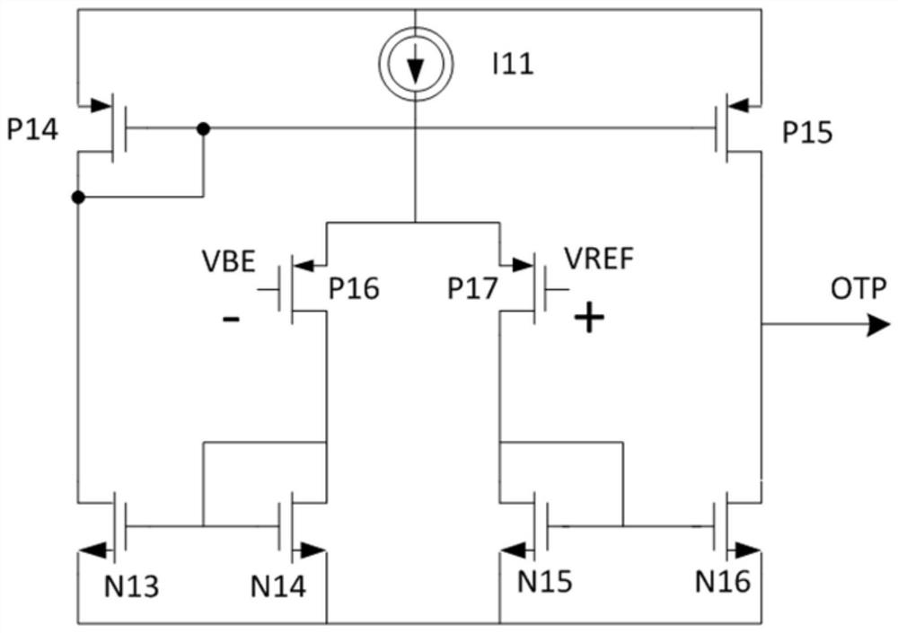
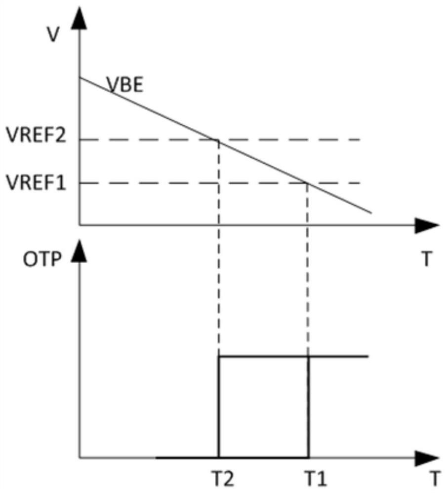
[0024] refer to Figures 4 to 5 As shown, the present invention provides an over-temperature protection circuit, including a resistor R23, a resistor R21, a transistor Q21, a comparator 1 with a hysteresis function, a voltage feedback loop module 2, and a first connected to the voltage feedback loop module 2 A current mirror 3; one end of the resistor R23 is connected to the voltage feedback loop module 2, and the other end of the resistor R23 is grounded; one end of the resistor R21 and the emitter of the triode Q21 are connected to the first current mirror 3, and the resistor R21 The other end of the transistor Q21 and the collector of the transistor Q21 are both connected to the resistor R23 and then grounded, and the base of the transistor Q21 is also connected to the collector of the transistor Q21; the non-inverting input terminal of th...


PUM


Abstract

The invention discloses an over-temperature protection circuit which comprises a resistor R23, a resistor R21, a triode Q21, a comparator with a hysteresis function, a voltage feedback loop module and a first current mirror connected with the voltage feedback loop module. One end of the resistor R23 is connected with the voltage feedback loop module, and the other end of the resistor R23 is grounded; one end of the resistor R21 and an emitting electrode of the triode Q21 are both connected with the first current mirror, and the other end of the resistor R21 and a collecting electrode of the triode Q21 are both connected with the resistor R23 and then grounded. The hysteresis function is realized in the comparator, the chip area can be reduced, the cost is saved, specifically, a switch of an internal circuit is controlled through an output signal of the comparator, so that the equivalent size of a load MOS (Metal Oxide Semiconductor) tube is changed, the equivalent width-length ratio of the load MOS tube is controlled, the hysteresis function is further realized, and the over-temperature protection circuit is simple and convenient.

Description

technical field [0001] The invention relates to the technical field of over-temperature protection, in particular to an over-temperature protection circuit. Background technique [0002] Power supply integrated circuit products have increasingly penetrated into all aspects of modern life. As a protection mechanism, the over-temperature shutdown function can effectively shut down the circuit when the chip temperature is too high, thereby avoiding abnormal circuit function or burning. The current over-temperature protection circuit is generally realized by using a comparator to compare a reference voltage that does not change with temperature and a voltage with a negative temperature coefficient that decreases with temperature. Among them, the hysteresis function is achieved by changing the reference voltage. The implementation of voltage is more complicated. Contents of the invention [0003] The purpose of the present invention is to provide an over-temperature protection...

Claims


Application Information

Patent Timeline
IPC IPC(8): G05F1/567
CPCG05F1/567
Inventor 孙金星
Owner SHENZHEN LOWPOWER SEMICON CO LTD
Features
  • R&D
  • Intellectual Property
  • Life Sciences
  • Materials
  • Tech Scout
  • Unparalleled Data Quality
  • Higher Quality Content
  • 60% Fewer Hallucinations
Learn More