Low-profile filtering antenna with broadband external suppression

A filtering antenna and low-profile technology, applied in antennas, resonant antennas, electrical short antennas, etc., can solve the problem of patch filter antennas without out-of-band harmonic suppression

Active Publication Date: 2021-09-10
XIDIAN UNIV
View PDF14 Cites 6 Cited by
  • Summary
  • Abstract
  • Description
  • Claims
  • Application Information

AI Technical Summary

Problems solved by technology

[0007] The invention solves the technical problem that the patch filter antenna has no good out-of-band harmonic suppression

Method used


Image

  • Low-profile filtering antenna with broadband external suppression
  • Low-profile filtering antenna with broadband external suppression
  • Low-profile filtering antenna with broadband external suppression

Examples


Embodiment 1

[0023] With the continuous development of communication systems in recent years, more and more functions have been added, and the manufacturing has become more and more precise. The requirements for multi-function and miniaturization have gradually become common. Patch antennas are widely used because they are easy to integrate and manufacture, but signal interference in communication Affecting the communication quality, the patch filter antenna can filter out the interference signal, but the usual patch filter antenna can only suppress the interference signal near the passband or the structure is relatively complicated, and will still be affected by high-frequency harmonics. Research and Experiment Design a low-profile filter antenna with out-of-band rejection.

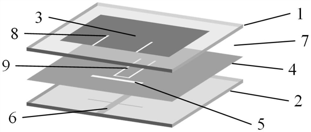
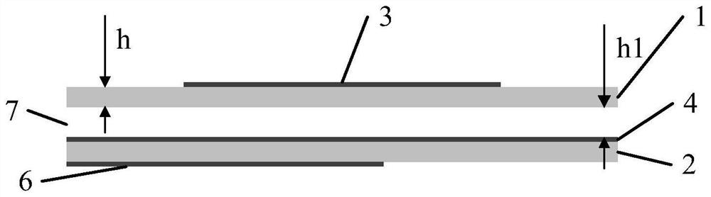
[0024] The present invention is a filter antenna with low profile and broadband external suppression, including a dielectric substrate, a metal radiation patch, a metal floor and a microstrip feeder printed on the die...

Embodiment 2

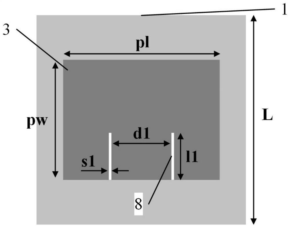
[0027] The overall composition of a filter antenna with a low-profile and out-of-band suppression is the same as in Embodiment 1, see image 3 , the rectangular double-slit structure 8 etched on the rectangular metal radiation patch 3 of the present invention forms a radiation zero point at high frequency. The width s1 of the 8 lines of the rectangular double-slit structure ranges from 0.3-0.8mm, the range of the length l1 ranges from 12-13mm, and the range of the distance d1 ranges from 14-16mm.

[0028] In this example, the rectangular double-slit structure 8 line width s1 is selected as 0.3 mm, the range of length l1 is 12 mm, and the range of distance d1 is 14 mm. This selection is suitable for higher frequency antennas.

Embodiment 3

[0030] The overall composition of a low-profile filter antenna with broadband out-of-band suppression is the same as in Embodiment 1-2. In this example, the width s1 of the rectangular double-slit structure 8 lines is 0.8 mm, the range of length l1 is 13 mm, and the range of distance d1 is 16 mm. This selection is suitable for lower frequency antennas.


PUM


Abstract

The invention discloses a low-profile filtering antenna with broadband external suppression and aims to solve the technical problem that a patch filtering antenna does not have good out-of-band suppression. The antenna comprises two dielectric substrates which are sequentially stacked from top to bottom; a rectangular metal radiation patch with a rectangular double-slit structure is printed and etched on the upper surface of the first dielectric substrate to form zero radiation at a high-frequency position; the upper surface and the lower surface of the second dielectric substrate are printed with a metal floor and a cross-shaped metal microstrip feeder respectively, a transparent rectangular gap and a U-shaped gap are etched in the metal floor, and the U-shaped gap is located in the center of the metal floor to form radiation zero at a low frequency; an air layer exists between the first dielectric substrate and the second dielectric substrate. Filter structures are arranged on the upper dielectric substrate and the lower dielectric substrate respectively, radiation zero points at the high frequency and the low frequency are generated respectively; a cross-shaped feeder line is additionally arranged; the out-of-band rejection range is increased; the passband selectivity is improved; and the out-of-band gain level is reduced. The antenna can be applied to a wireless communication system.

Description

technical field [0001] The invention belongs to the technical field of antennas, and relates to a patch type filter antenna, in particular to a filter antenna with low profile and broadband out-of-band suppression, which is suitable for communication systems requiring an easily integrated structure and capable of suppressing interference signals. Background technique [0002] Due to the development of the communication system, various parts of the communication system have undergone great changes and progress. At the beginning, the system only needs to realize simple signal transmission, and the function is relatively single, and the impact of noise on the communication system is not considered. Modern communication has developed more and more forms. In order to achieve better communication effects and enhance the ability to resist harsh environments, the requirements for communication equipment are getting higher and higher. [0003] With the increasing use of various freq...

Claims


Application Information

Patent Timeline
Patent Type & Authority Applications(China)
IPC IPC(8): H01Q9/04H01Q1/48H01Q1/38H01Q1/50
CPCH01Q9/0414H01Q9/045H01Q1/48H01Q1/50H01Q1/38
Inventor 张立孙季秋翁子彬鲁昊曹志勋
Owner XIDIAN UNIV
Why Eureka
Try Eureka