
A liquid discharge control device and method for a supergravity centrifugal model

A centrifugal model and emission control technology, which is applied in the direction of centrifuges, comprehensive factory control, centrifuges with rotating drums, etc., can solve whether the success of the test is full of variables, intervene and adjust control variables, and increase the difficulty of model making and other issues to achieve the effects of saving analysis costs, timely feedback and changes, and simple and easy control methods

Active Publication Date: 2022-05-31
ZHEJIANG UNIV
View PDF10 Cites 0 Cited by
  • Summary
  • Abstract
  • Description
  • Claims
  • Application Information

AI Technical Summary

Problems solved by technology

[0008] (1) In the existing problem of liquid discharge in a supergravity environment, the purpose of drainage and water storage is basically achieved through the independent device inside the model box, which inevitably requires the attached device to run smoothly in a supergravity environment, especially the speed regulation The operation of valves and motors is full of variables due to the great changes in the working environment.
[0009] (2) The existing control device and the model box are packaged together in the hypergravity cabin, and the discharge of liquid is basically carried out spontaneously or triggered passively through preset thresholds and other conditions. Because the liquid discharge process depends on The autonomous operation of the control system, the subjective initiative of the test personnel cannot effectively guide the whole process of the test, let alone give timely feedback, and cannot intervene and adjust the control variables in real time according to the requirements. The whole process is mechanically strong, with low precision, low efficiency and high failure rate.
[0010] (3) The existing liquid discharge system is obtained by modifying the model box, which will increase the difficulty of model making, and at the same time, this highly personalized liquid control system hinders its function from being transplanted to another different test. Low

Method used


Image

  • A liquid discharge control device and method for a supergravity centrifugal model
  • A liquid discharge control device and method for a supergravity centrifugal model
  • A liquid discharge control device and method for a supergravity centrifugal model

Examples


Embodiment Construction

[0060] The present invention will be further described below in conjunction with the accompanying drawings and specific embodiments.

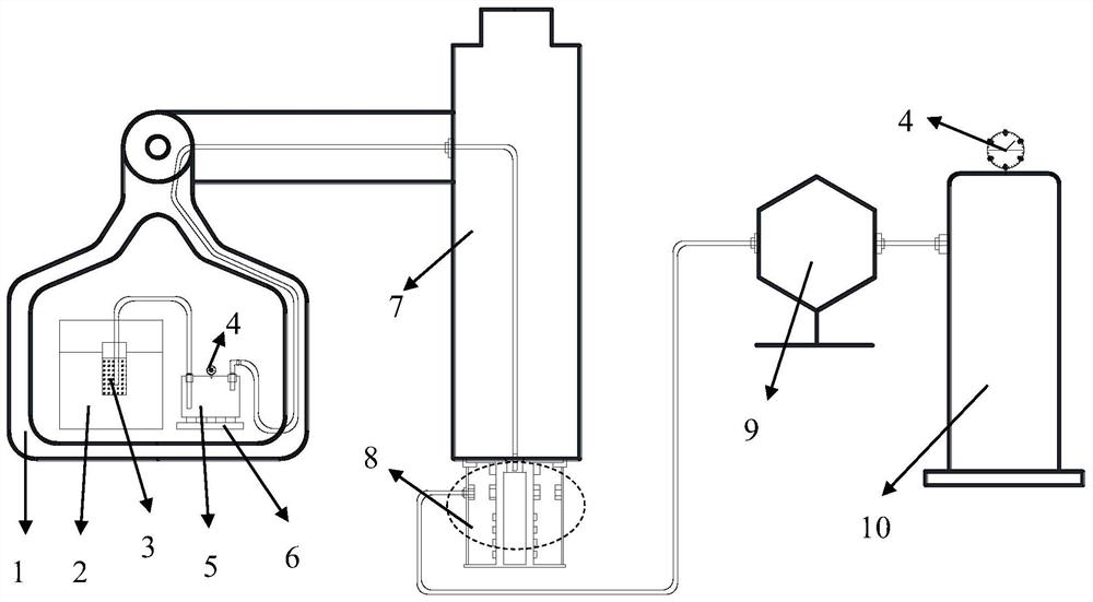
[0064] The trachea pipeline is connected to the liquid ring device 8 after extending from the test end hanging basket 1 through the rotating arm and the rotating shaft of the hypergravity centrifuge.

[0066] There is a vacuum pump in the vacuum regulation system 10, and the vacuum pump is used for vacuuming operation. Vacuum regulation system 10 jobs

[0070] Z

[0073] Z

[0078] is to use manual adjustment to pre-adjust to an empirical value, and then enter the system automatic adjustment link, because I

[0081] Specifically, the liquid discharge rate ΔM* / Δt can be compared with the set liquid quality control parameter Z


PUM


Abstract

The invention discloses a liquid discharge control device and method for a supergravity centrifugal model. The centrifuge liquid discharge control system is composed of the centrifugal model of the supergravity cabin, the closed liquid storage tank, the centrifuge liquid ring device and the constant gravity vacuum adjustment system. The liquid quality or vacuum degree control parameters of the closed liquid storage tank are obtained, and then the vacuum The adjustment system adjusts the vacuum pressure in real time to meet the needs of the closed liquid storage tank, so as to achieve the purpose of high-precision emission control standards that meet the needs of different model tests. The method of the present invention intervenes in the supergravity model liquid discharge control test in real time by forming a dual-environment collaboration platform of supergravity-normal gravity, and realizes the result of high-precision and high-efficiency control of the liquid discharge inside the model, and the control method can be simple and easy It is applicable to other batches of experiments, which is scientific and easy to popularize.

Description

A kind of supergravity centrifugal model liquid discharge control device and method technical field The invention belongs to control device and method under a kind of hypergravity of hypergravity centrifuge model test field, concrete It relates to a liquid discharge control device and method for a hypergravity centrifugal model test. Background technique Hypergravity centrifuge experiment is the scientific research method of new development in the field of geotechnical engineering in the new century, and its reduction engineering On-site stress conditions, reducing the scale of the structure, accelerating the time process, including the internal seepage process of the soil and other important characteristics have become An extremely effective research tool that has played a unique role in major national development planning projects. However, because the centrifuge The particularity-closedness of the operating environment often results in the inability to accurately...

Claims


Application Information

Patent Timeline
Patent Type & Authority Patents(China)
IPC IPC(8): B04B1/00B04B11/02
CPCB04B1/00B04B11/02Y02P90/02
Inventor 闫子壮李超黄根清王剑李俊超邱冰静洪帅
Owner ZHEJIANG UNIV
Learn More