
Supergravity centrifugal model liquid discharge control device and method

A centrifugal model, emission control technology, used in centrifuges, full plant control, centrifuges with rotating drums, etc., can solve problems such as low efficiency, inability to effectively guide, and inability to give timely feedback

Active Publication Date: 2021-09-14
ZHEJIANG UNIV
View PDF10 Cites 0 Cited by
  • Summary
  • Abstract
  • Description
  • Claims
  • Application Information

AI Technical Summary

Problems solved by technology

[0008] (1) In the existing problem of liquid discharge in a supergravity environment, the purpose of drainage and water storage is basically achieved through the independent device inside the model box, which inevitably requires the attached device to run smoothly in a supergravity environment, especially the speed regulation The operation of valves and motors is full of variables due to the great changes in the working environment.
[0009] (2) The existing control device and the model box are packaged together in the hypergravity cabin, and the discharge of liquid is basically carried out spontaneously or triggered passively through preset thresholds and other conditions. Because the liquid discharge process depends on The autonomous operation of the control system, the subjective initiative of the test personnel cannot effectively guide the whole process of the test, let alone give timely feedback, and cannot intervene and adjust the control variables in real time according to the requirements. The whole process is mechanically strong, with low precision, low efficiency and high failure rate.
[0010] (3) The existing liquid discharge system is obtained by modifying the model box, which will increase the difficulty of model making, and at the same time, this highly personalized liquid control system hinders its function from being transplanted to another different test. Low

Method used


Image

  • Supergravity centrifugal model liquid discharge control device and method
  • Supergravity centrifugal model liquid discharge control device and method
  • Supergravity centrifugal model liquid discharge control device and method

Examples


Embodiment Construction

[0060] The present invention will be further described below in conjunction with the accompanying drawings and specific embodiments.

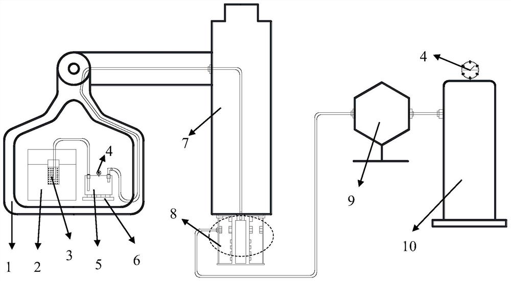
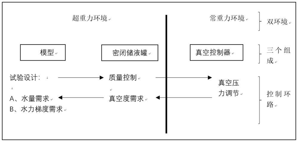
[0061] Such as figure 1 As shown, the supergravity centrifuge includes a supergravity centrifuge main body 7 and a test end hanging basket 1, a centrifugal model 2 is placed in the test end hanging basket 1, and the bottom of the centrifugal model 2 is fixed on the inner bottom surface of the test end hanging basket 1; Liquid area 3, pressure gauge 4, closed liquid storage tank 5, precision electronic scale 6, liquid ring device 8, proportional regulating valve 9 and vacuum regulating system 10; proportional regulating valve 9 and vacuum regulating system 10 are placed in a constant gravity environment, The rest of the devices were placed in a hypergravity environment.

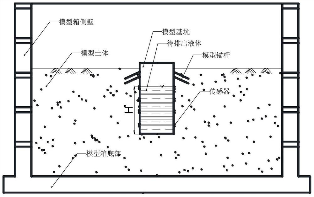
[0062] The liquid area 3 to be drained is placed in the centrifugal model 2, the precision electronic scale 6 and the closed liquid storage tank 5 are placed in the test end ...


PUM


Abstract

The invention discloses a supergravity centrifugal model liquid discharge control device and method. A centrifugal liquid discharge control system is composed of a centrifugal model of a super-gravity cabin, a closed liquid storage tank, a centrifugal machine liquid ring device and a constant-gravity vacuum adjusting system, liquid quality or vacuum degree control parameters of the closed liquid storage tank are obtained, and then the vacuum adjusting system adjusts vacuum pressure in real time to meet the requirements of the closed liquid storage tank. Therefore, a purpose of meeting emission control standards required by different model tests with high precision is achieved. According to the method, a supergravity model liquid discharge control test is intervened in real time by forming a supergravity-constant gravity dual-environment cooperation platform, a result of high-precision and high-efficiency control over liquid discharge in the model is achieved, and the control method can be easily and conveniently applied to other batches of tests, is high in scientificity and is easy to popularize.

Description

technical field [0001] The invention belongs to a control device and method under supergravity in the field of supergravity centrifuge model tests, and in particular relates to a liquid discharge control device and method for supergravity centrifuge model tests. Background technique [0002] The supergravity centrifuge experiment is a newly developed scientific research method in the field of geotechnical engineering in the new century. It has become an extremely effective method for restoring the stress conditions of the engineering site, reducing the scale of the structure, accelerating the time process, and including the internal seepage process of the soil. The research tool has played a unique role in major national development planning projects. However, due to the particularity of the operating environment of the centrifuge - the closed nature, it is often impossible to accurately and effectively intervene and control the variables of the physical model in the cabin. ...

Claims


Application Information

Patent Timeline
Patent Type & Authority Applications(China)
IPC IPC(8): B04B1/00B04B11/02
CPCB04B1/00B04B11/02Y02P90/02
Inventor 闫子壮李超黄根清王剑李俊超邱冰静洪帅
Owner ZHEJIANG UNIV
Learn More