Fiber winding machine and winding method

A technology of filament winding machine and connecting flange, which is applied to other household appliances, household appliances, household components, etc., can solve the problems of poor pressure resistance, low production efficiency, and reduced fiber material strength.

Pending Publication Date: 2021-09-14
XIAN YINGLIKE ELECTRIC TECH CO LTD
View PDF7 Cites 1 Cited by
  • Summary
  • Abstract
  • Description
  • Claims
  • Application Information

AI Technical Summary

Problems solved by technology

However, the production efficiency of the traditional filament winding process is low. A bundle of yarns is reciprocated and wound many times to cover a longitudinal winding layer. During the winding process, the reciprocating longitudinal yarns will inevitably collide with the previously wound yarns during spiral winding. Overlapping occurs and causes a large number of microbends to the fi

Method used


Image

  • Fiber winding machine and winding method
  • Fiber winding machine and winding method
  • Fiber winding machine and winding method

Examples


Embodiment 1

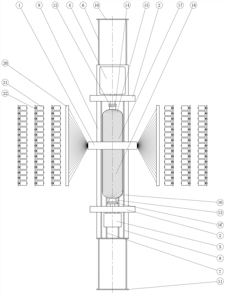
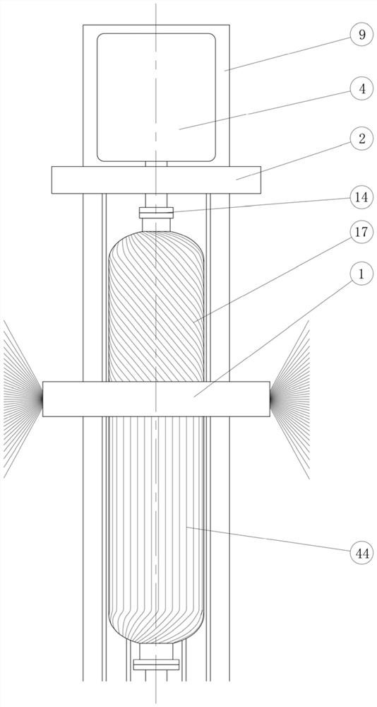
[0036] see figure 1 , Figure 3 ~ Figure 6, a kind of fiber winding machine that the present invention proposes, comprises vertical moving car 9, warp yarn winding head 1, weft yarn winding head 2 and computer control system, and warp yarn winding head 1 comprises a group of wire guides 28 distributed on the same ring , each yarn guide 28 has a warp yarn 29 to pass through, the warp yarn at the rear end of the yarn guide 28 is connected to the warp yarn barrel 21, the warp yarn at the front end of the yarn guide 28 is wound on the mandrel 39, and the circle around the yarn guide 28 The diameter is slightly larger than the diameter of the mandrel 39 cylindrical sections; the warp winding head 1 is provided with a pinch mechanism on both longitudinal sides, and the pinch mechanism on each side is composed of several evenly distributed inner circle ring hoops 27 and telescopic mechanisms. The telescopic mechanism can be synchronously telescopic along the radial direction;

[00...

Embodiment 2

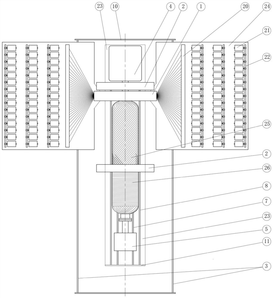
[0053] see Figure 2 to Figure 6 , A kind of fiber winding machine that the present invention proposes, comprises machine base 23, main locomotive 4, auxiliary locomotive 5, warp yarn winding trolley 24, weft yarn winding head 2 and computer control system. The support 23 is fixed on the ground, and the fixed main headstock 4 and the auxiliary headstock 5 that can move longitudinally and lock on the track 7 on the support 23 are installed above the support 23; A set of third rails 8 for longitudinal movement of the weft yarn winding head 2 that usually stays next to the main and auxiliary locomotives is specially provided; the warp yarn winding head 1 and the creel 22 are installed on the warp yarn winding trolley 24, and the warp yarn winding trolley 24 is located on the winding machine On the parallel tracks 3 on both sides of the support 23, the warp yarn winding dolly 24 is provided with a traveling drive servo motor, which can be controlled by a computer to drive the warp...


PUM


Abstract

The invention discloses a fiber winding machine and a winding method. The fiber winding machine comprises a moving device, a core mold, a warp winding head, weft winding heads and warp supply devices; the warp winding head is arranged on the outer side of the moving device in a surrounding mode, the core mold is arranged on the moving device, and the core mold and the warp winding head are coaxially arranged; the weft winding heads are arranged at the positions, on the two sides of the warp winding head, of the moving device; and the warp supply devices are arranged on the two sides of the moving device and connected with the warp winding head. The helical angles of warps on the same layer flat laid on a cylindrical surface relative to the axis of the core mold are the same, and mutual overlapping does not exist; the adjacent warp layers in the radial direction of the cylindrical surface do not overlap with each other, so that cross bending of fibers is reduced, the mechanical property of the high-strength fibers can be better exerted, and winding bodies are firmer and lighter; and compared with a traditional fiber winding machine, the production efficiency of the winding machine can be greatly improved.

Description

technical field [0001] The invention belongs to the technical field of manufacturing high-pressure containers of composite materials, and in particular relates to a fiber winding machine and a winding method. Background technique [0002] Combustion chamber shells of composite solid rocket motors are manufactured by high-strength fiber winding process. The body is both light and strong. However, the production efficiency of the traditional filament winding process is low. A bundle of yarns is reciprocated and wound many times to cover a longitudinal winding layer. During the winding process, the reciprocating longitudinal yarns will inevitably collide with the previously wound yarns during spiral winding. Overlapping occurs and causes a large number of micro-bends to the fiber bundles, which reduces the effective use of the strength of the fiber material; especially frequent overlapping at the two ends of the head will form a lot of gaps under the yarn, which has relatively...

Claims


Application Information

Patent Timeline
IPC IPC(8): B29C53/60B29C53/80B29C53/84B29L31/30
CPCB29C53/585B29C53/60B29C53/8008B29C53/845B29L2031/3097
Inventor 吉少波李杰李凤珍朱晓军谭鑫胡国斌
Owner XIAN YINGLIKE ELECTRIC TECH CO LTD
Why Eureka
Try Eureka