Strip detecting apparatus

A technology for testing equipment and test pieces, which is applied in measuring devices, image data processing, and induction recording carriers, etc., and can solve problems such as shaking, image position offset and skew, and image interpretation errors

Pending Publication Date: 2021-09-14
林裕城
View PDF0 Cites 0 Cited by
  • Summary
  • Abstract
  • Description
  • Claims
  • Application Information

AI Technical Summary

Problems solved by technology

[0003] However, in the prior art, the test results are usually judged by visually comparing the colors presented by the test pieces. This method will not only result in a time-consuming and labor-intensive manual comparison process, but also be prone to visual colorimetric interpretation. The problem of error, although the image recognition method has been developed to replace the above-mentioned visual colorimetric method for more accurate and objective interpretation of the test results, but because this method usually requires the user to take a picture of the color guide and the test test by himself. Therefore, there are often problems such as image position offset and skew, angle inclination, shaking, etc., which cause image interpretation errors and greatly affect the accuracy of test results.

Method used


Image

  • Strip detecting apparatus
  • Strip detecting apparatus
  • Strip detecting apparatus

Examples


Embodiment Construction

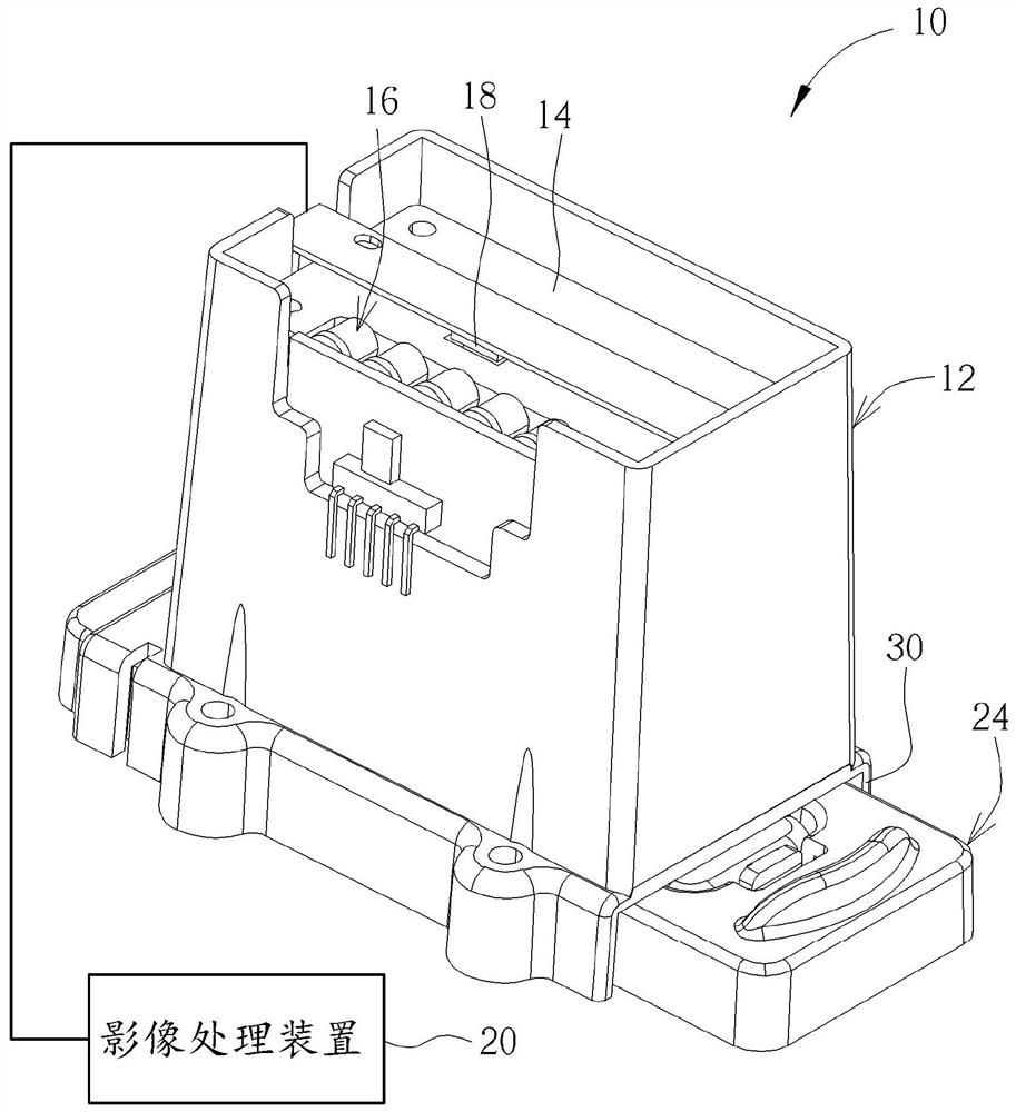
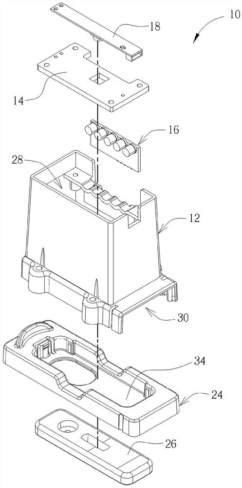
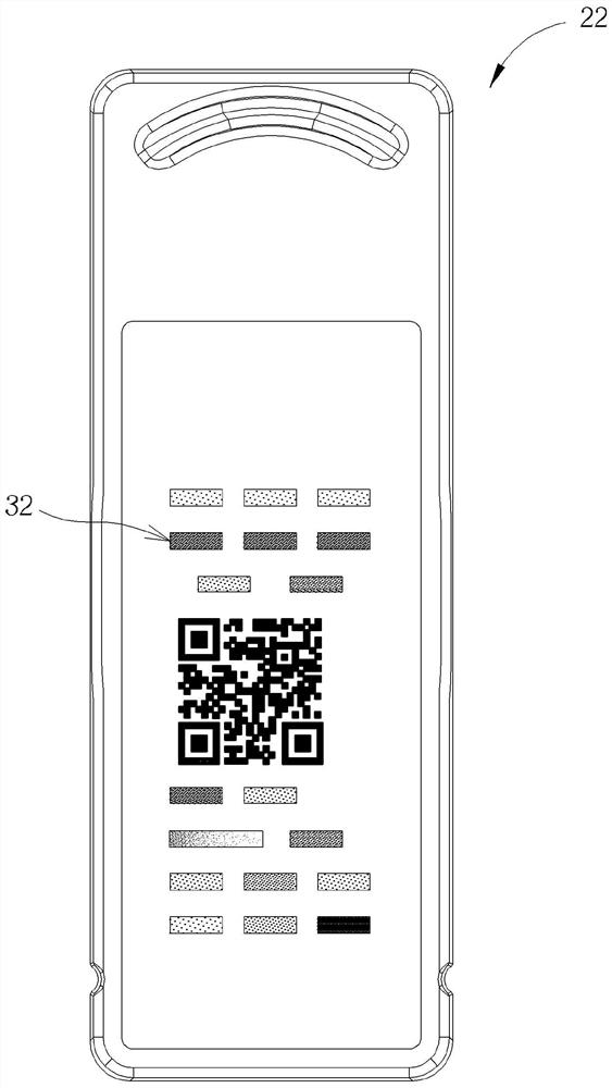
[0014] see figure 1 , figure 2 as well as image 3 , figure 1 It is an assembly schematic diagram of a test piece testing device 10 proposed according to an embodiment of the present invention, figure 2 for figure 1 Exploded schematic diagram of the test piece testing device 10, image 3 It is a top view of an optical correction card 22 proposed according to an embodiment of the present invention, such as figure 1 , figure 2 as well as image 3 As shown, the test piece detection equipment 10 includes a detection dark box 12, a light guide plate 14, a light source 16, an image capture device 18, and an image processing device 20 (in figure 1 (shown briefly as a functional block diagram), an optical calibration card 22 , a test piece carrier 24 , and a detection test piece 26 . The detection dark box 12 has a detection chamber 28 and an insertion port 30 to provide a darkroom detection environment. The light guide plate 14 is arranged at the position above the detecti...


PUM


Abstract

A strip detecting apparatus includes a black box, a light guide plate disposed on the black box, a light source, an optical calibration card, a strip platform, a test strip contained in the strip platform, an image capturing device and an image processing device. The light source is disposed on the black box to emit light toward the black box via the light guide plate. The image capturing device is disposed on the black box for respectively capturing an optical calibration image and a detection image when the optical calibration card and the strip platform are inserted into the black box respectively. The image processing device is coupled to the image capturing device for calibrating relationship information between the concentration and the grayscale value of the test strip according to the optical calibration image and for generating a test result according to the calibrated relationship information and the detection image.

Description

technical field [0001] The present invention relates to a test piece detection device, especially a test piece that uses a detection dark box and performs optical correction through an optical correction card inserted therein and interprets the detection results of the test piece on the test piece carrier inserted therein. Chip testing equipment. Background technique [0002] With the development of medical testing technology, many applications of rapid screening test strips have emerged, such as urine test strips, fecal occult blood and gastric pylori test strips, etc., to help users quickly monitor their own health conditions. initial understanding. A common detection method is to contact the corresponding detection test strip (such as urine ten-item test strip, lateral flow chromatography immunoreaction test strip, etc.) with the specimen to be detected and then use the color scale line on the color guide The color of the specimen is compared with the color presented by...

Claims


Application Information

Patent Timeline
Patent Type & Authority Applications(China)
IPC IPC(8): G01N21/84G01N21/01
CPCG01N21/8483G01N21/01G01N2021/0112G01N2021/7759G01N21/78G01N21/274G01N2201/062G01N2201/08G01N2201/127B01L9/527B01L3/50273B01L2300/0825B01L2300/021G06T2207/30004G06T2207/10024G06T7/0014G01N33/54386G01N21/77B01L3/5023G06T7/0012G06T7/80G06T7/70G06K7/1417G06K7/10722G06K19/06037
Inventor 林裕城翁维谦林凯文
Owner 林裕城
Why Eureka
Try Eureka