A high-efficiency vertical dry stirring mill and its application

A mill and vertical technology, applied in the field of high-efficiency vertical dry stirring mill, can solve the problems of difficulty in controlling the fineness of finished products, poor separation effect of finished products, and low grinding efficiency, so as to achieve clear feeding and discharging paths, Small working resistance and improved grinding efficiency

Active Publication Date: 2022-07-12
TIANJIN CEMENT IND DESIGN & RES INST
View PDF17 Cites 0 Cited by
  • Summary
  • Abstract
  • Description
  • Claims
  • Application Information

AI Technical Summary

Problems solved by technology

[0010] In order to solve the problems of low grinding efficiency, poor product separation effect, difficult heat dissipation, difficulty in controlling the fineness of finished products, serious over-grinding and other problems of the existing dry vertical stirring mill, the present invention provides a high-efficiency vertical dry stirring mill, Improve the grinding efficiency of the dry vertical stirring mill, accurately control the product fineness, and improve the reliability and stability of the equipment

Method used


Image

  • A high-efficiency vertical dry stirring mill and its application
  • A high-efficiency vertical dry stirring mill and its application
  • A high-efficiency vertical dry stirring mill and its application

Examples


Embodiment Construction

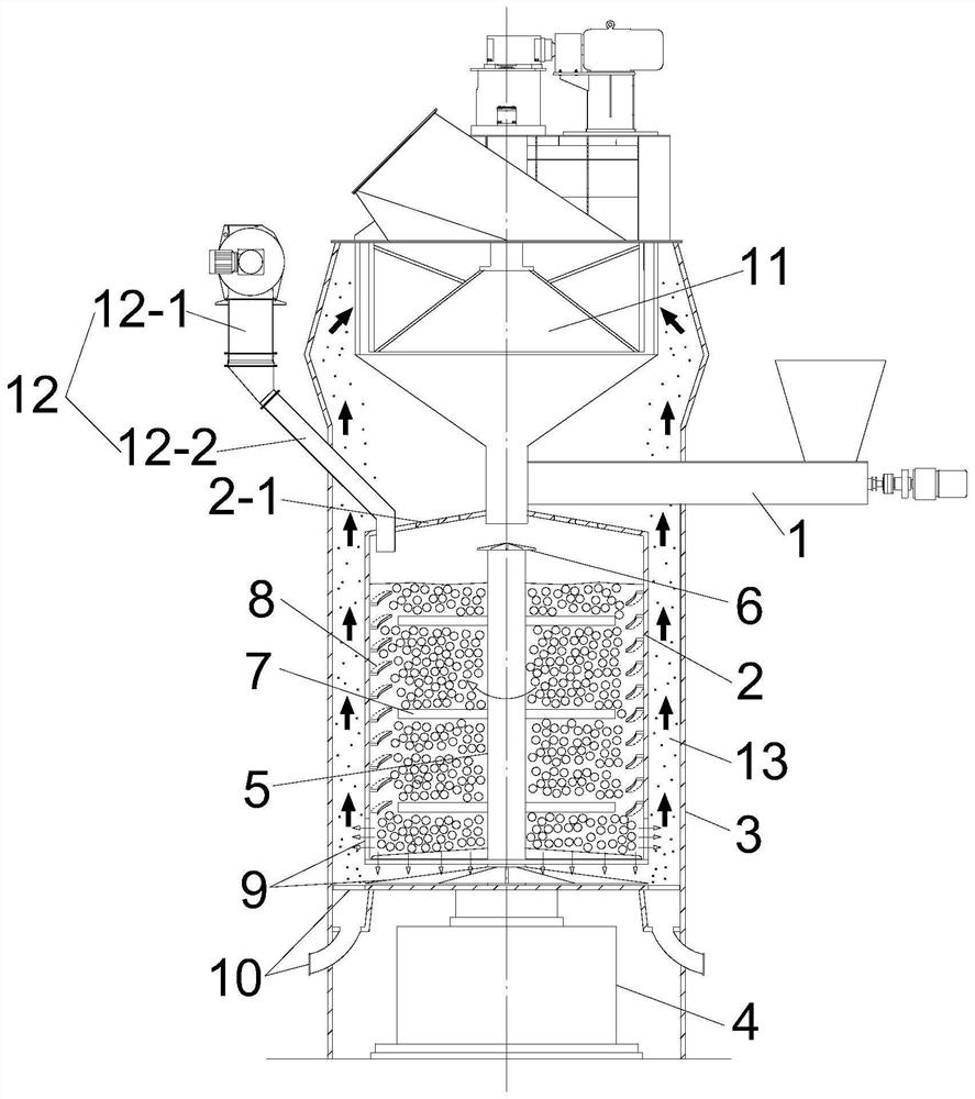
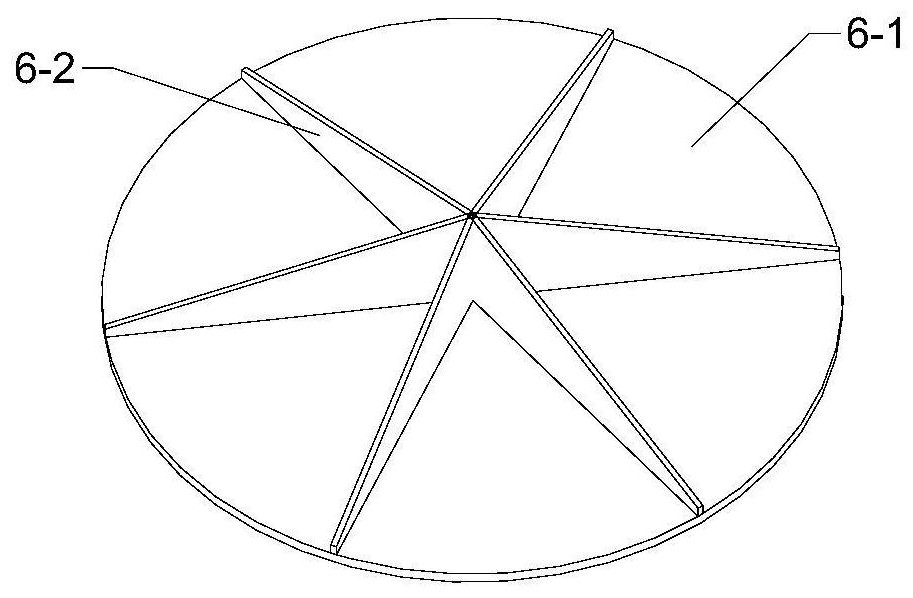
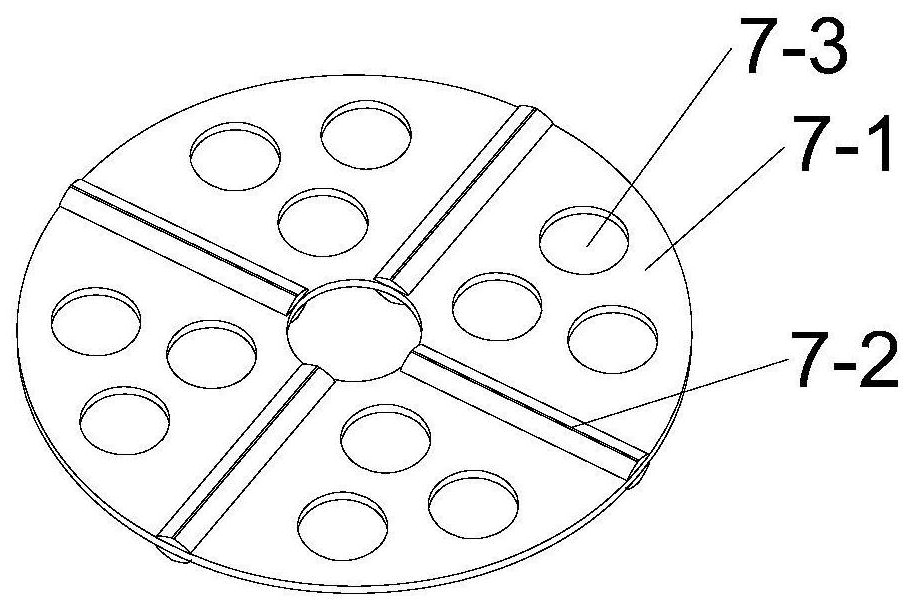
[0047] In order to make the objectives, technical solutions and advantages of the present invention clearer, the present invention will be further described in detail below with reference to the embodiments and the accompanying drawings. It should be understood that the specific embodiments described herein are only used to explain the present invention, but not to limit the present invention.

[0048] In the description of the present invention, it should be noted that the orientations or positional relationships indicated by the terms "upper", "lower", "top", "bottom", "inner", "outer", etc. are based on those shown in the accompanying drawings. The orientation or positional relationship is only for the convenience of describing the present invention and simplifying the description, rather than indicating or implying that the indicated device or element must have a specific orientation, be constructed and operated in a specific orientation, and therefore should not be constru...


PUM


Abstract

The invention discloses a high-efficiency vertical dry stirring mill and its application. The mill comprises a casing, a screw feeder, a grinding drum, a main shaft, a stirrer, an activated lining plate, a discharge device, a driving device, a powder selection Machine and air supply device; the powder separator, screw feeder, grinding drum, discharge device, driving device, the coarse particle return pipe of the powder separator and the discharge of the screw feeder are installed in the shell from top to bottom. The ends are connected with the top of the grinding cylinder, the grinding cylinder is provided with a main shaft and a stirrer, the agitator is fixed on the main shaft, the inner wall of the grinding cylinder is provided with an activated lining plate, and the discharging device is arranged at the bottom of the grinding cylinder and fixed on the main shaft; the main shaft is The bottom is connected with the driving device; the space between the grinding cylinder and the outer casing forms an annular air chamber, and the air supply device is arranged below the discharging device and faces the annular air chamber. The invention has high grinding efficiency, good separation effect of finished products, no over-grinding phenomenon, good heat dissipation, precise control of product fineness, reduced energy consumption, and improved equipment reliability and stability.

Description

technical field [0001] The invention relates to the technical field of stirring mills, in particular to a high-efficiency vertical dry stirring mill and its application. Background technique [0002] The stirring mill consists of a driving device, a barrel, a stirrer, and a grinding medium. The barrel is usually a cylinder. The agitator is usually a screw type, a rod-pin type and a disc type. The grinding medium is usually steel balls, corundum balls, Zirconium ball or natural river sand, pebbles and other spherical media. When working, the cylinder of the agitating mill is stationary, the driving device drives the agitator to rotate, and the agitator directly applies the power to the grinding medium, so that the grinding medium and the material perform multi-dimensional circular motion and self-rotating motion, and the grinding, shearing and impacting of the medium balls Function to achieve effective grinding of materials. The grinding efficiency depends on the total numb...

Claims


Application Information

Patent Timeline
Patent Type & Authority Patents(China)
IPC IPC(8): B02C17/10B02C17/16B02C17/18B02C17/22B02C23/24B02C23/12B02C23/02
CPCB02C17/163B02C17/10B02C17/22B02C17/183B02C17/1815B02C17/1875B02C17/1845Y02P40/10
Inventor 刘畅杜鑫聂文海柴星腾豆海建
Owner TIANJIN CEMENT IND DESIGN & RES INST
Why Eureka
Try Eureka