Optical control device and method for coating thickness

An optical control and laser technology, which is applied in sputtering coating, vacuum evaporation coating, ion implantation coating, etc., can solve the problems of misjudgment of coating termination conditions, demanding stability requirements, complex systems, etc., and achieve reduced stability and rotation position detection accuracy requirements, to achieve real-time optimization, the effect of a simple system

Active Publication Date: 2021-09-17
INST OF OPTICS & ELECTRONICS - CHINESE ACAD OF SCI
View PDF6 Cites 0 Cited by
  • Summary
  • Abstract
  • Description
  • Claims
  • Application Information

AI Technical Summary

Problems solved by technology

However, the film thickness optical control device based on light source also has a series of disadvantages.
Firstly, because the intensity of the light source after monochromatization is very small, it brings a lot of noise, which leads to misjudgment of the coating termination condition; secondly, the system is very complicated due to the wide application of structures such as gratings and monochrome slits. , high cost and very demanding stability requirements; in addition, the wavelength linewidth of monochromatic quasi-monochromatic light is usually above 1nm, and in some filter coatings with high requirements, the wider linewidth will also bring monitoring error

Method used


Image

  • Optical control device and method for coating thickness
  • Optical control device and method for coating thickness
  • Optical control device and method for coating thickness

Examples


Embodiment 1

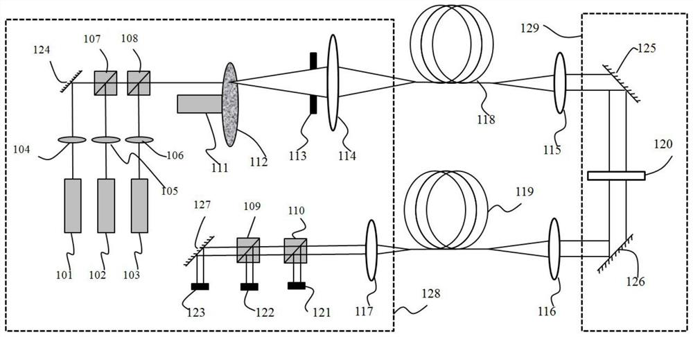
[0039] figure 1 Shows the structure of a coating thickness optical control device, the coating thickness optical control device includes three different wavelengths of the first laser 101, the second laser 102 and the third laser 103, the first lens group 104, the second lens group 105 and the third lens group 106, the first light splitting element 107, the second light splitting element 108, the third light splitting element 109 and the fourth light splitting element 110, the drive motor 111, the diffusion plate 112, the diaphragm 113, the first lens 114, the second light splitting element Two lens 115, the third lens 116 and the fourth lens 117, the first multimode fiber 118 and the second multimode fiber 119, the optical control test piece 120, the first optical power meter 121, the second optical power meter 122 and the third Optical power meter 123, optional first planar reflective element 124, second planar reflective element 125, third planar reflective element 126, and...

Embodiment 2

[0064] The following examples illustrate the method of using the coating thickness optical control device to control coating thickness and realize optical interference multilayer coating. by Ta 2 o 5 As a high refractive index material, SiO 2 As a low refractive index material, it should be noted that the high refractive index and low refractive index here are only relative concepts, and do not limit a certain refractive index or refractive index range to low or high refractive index. The double-sided polished fused silica glass substrate is used as a light control test piece to realize Figure 4 In the shown wavelength range of 400nm-1000nm, both the transmittance curve 401 and the reflectance curve 402 are close to the function of a 50% spectroscopic film. This implementation example only introduces the working mode of the thickness control device shown, and other various film systems can be realized by using the steps and methods.

[0065] Ta 2 o 5 film, SiO 2 The re...


PUM

PropertyMeasurementUnit
diameteraaaaaaaaaa
transmittivityaaaaaaaaaa

Abstract

The invention relates to an optical control device and method for the coating thickness. The device comprises one or more laser devices with different wavelengths, a light splitting optical element for splitting and combining lasers with different wavelengths, a scatter plate, a driving motor, a lens, a multimode optical fiber, an optical power meter, a light-operated test piece and a coating clamp. The lasers are converted into quasi-coherent light through the scatter plate which is driven by the driving motor to rotate, the quasi-coherent light is focused through the lens, enters the multimode optical fiber, is transmitted to a coating machine, is collimated through the lens and then enters the light-operated test piece, transmission light is focused through the lens, enters a second multimode optical fiber and is collimated and split at an optical fiber outlet, and the optical power meter is used for respectively measuring the power of emergent light with the different wavelengths and monitoring the transmissivity of light with the different wavelengths on the light-operated test piece, so that the coating thickness is controlled. The optical control device for the coating thickness has the advantages of simple structure, convenience in mounting and narrow monitoring light source line width, and can achieve thickness control in the high-precision optical film coating process.

Description

technical field [0001] The invention relates to the technical field of film coating, in particular to an optical control device and method for film thickness. Background technique [0002] An optical interference filter is an optical element that selectively modulates light of different wavelengths through the interference of multilayer films. Its performance is closely related to the thickness control accuracy of the multilayer films that make up the filter. The thickness of the film is the core technology of coating optical interference filters. The commonly used methods to control the film thickness include quartz monitor method, time control method and optical control method. The quartz monitor uses the relationship between the oscillation frequency of the quartz crystal and the thickness of the film deposited on the quartz crystal to determine the thickness of the deposited film. Since the position of the quartz monitor is usually different from the position of the fil...

Claims


Application Information

Patent Timeline
Patent Type & Authority Applications(China)
IPC IPC(8): C23C14/54C23C14/34
CPCC23C14/547C23C14/3442C23C16/52G01B11/0683G01B11/0633
Inventor 柳存定黎明杨伟
Owner INST OF OPTICS & ELECTRONICS - CHINESE ACAD OF SCI
Why Eureka
Try Eureka