Electroplating machining device convenient to adjust

A processing device and convenient technology, applied in the direction of electrolysis components, electrolysis process, cells, etc., can solve the problems of long waiting time, inability to freely adjust the height of the products to be plated, and inability to guarantee the smoothness requirements of the products to be plated, etc., to improve work efficiency, The effect of improving the plating effect

Pending Publication Date: 2021-09-17
厦门明佑电镀有限公司
View PDF0 Cites 2 Cited by
  • Summary
  • Abstract
  • Description
  • Claims
  • Application Information

AI Technical Summary

Problems solved by technology

[0002] The electroplating device is a tool that is often used in the electroplating industry, especially in the electroplating process of precision devices. It is necessary to design electroplating tools according to their own needs. The process is to use the principle of electrolysis to spread a layer of metal on the conductor. Electroplating It refers to a surface processing method in which the cations of the pre-plated metal in the plating solution are deposited on the surface of the base metal by electrolysis with the base metal to be plated as the cathode in the salt solution containing the pre-plated metal to form a coating. The performance of the coating is different from that of the base metal and has new features. According to the function of the coating, it is divided into protective coating, decorative coating and other functional coatings. During electroplating, the coati

Method used


Image

  • Electroplating machining device convenient to adjust
  • Electroplating machining device convenient to adjust
  • Electroplating machining device convenient to adjust

Examples


Embodiment Construction

[0019] The following will clearly and completely describe the technical solutions in the embodiments of the present invention with reference to the accompanying drawings in the embodiments of the present invention. Obviously, the described embodiments are only some, not all, embodiments of the present invention. Based on the embodiments of the present invention, all other embodiments obtained by persons of ordinary skill in the art without making creative efforts belong to the protection scope of the present invention.

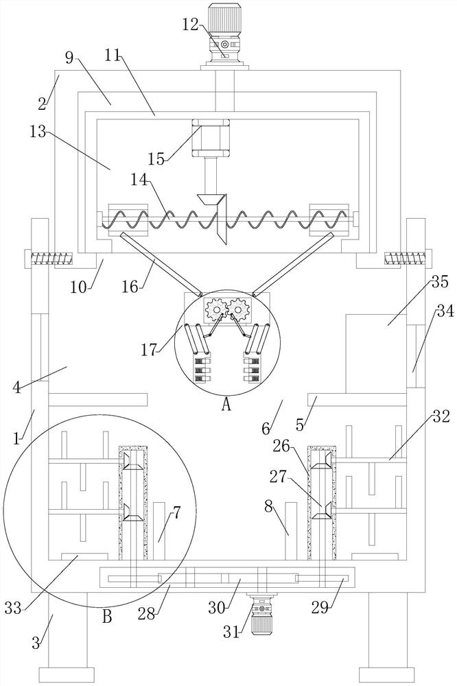
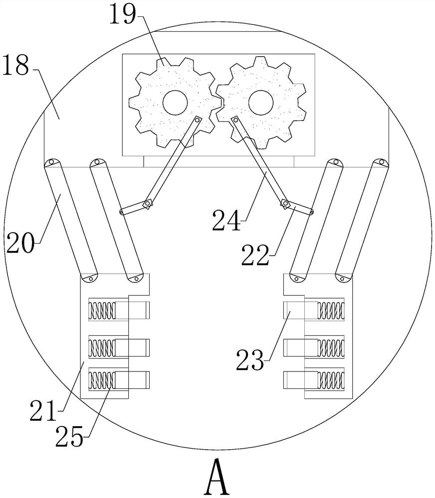
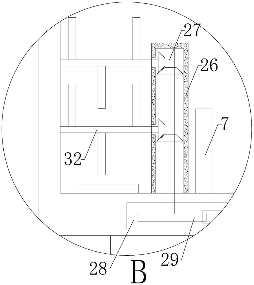
[0020] see Figure 1-3 , a conveniently adjustable electroplating processing device, comprising an electroplating pool 1 and a drive box 2, the bottom of the electroplating pool 1 is provided with a support leg 3, the top of the electroplating pool 1 is provided with a liquid storage tank 4, and the middle of the liquid storage tank 4 The positioning plate 5 is set at the position, the positioning hole 6 is set at the middle position of the positioning plate 5...


PUM


Abstract

An electroplating machining device convenient to adjust comprises an electroplating tank and a driving box, wherein supporting legs are arranged at the bottom end of the electroplating tank, a liquid storage tank is arranged at the top end of the electroplating tank, a positioning plate is arranged in the middle of the liquid storage tank, a positioning hole is formed in the middle of the positioning plate, and a cathode bar and an anode bar are arranged at the left side and the right side of the bottom end of the liquid storage tank respectively; and the driving box is arranged at the upper portion of the inner wall of the liquid storage tank, a driving cavity is formed in the driving box, and a driving hole is formed in the bottom end of the driving cavity. Through arrangement of a clamping device, a workpiece can be conveniently clamped; through arrangement of a threaded rod, threaded pipes, supporting rods, the clamping device and a driving motor, after the workpiece is clamped in the clamping device, the workpiece can be conveniently clamped in the clamping device, the working motor works to drive the threaded rod to rotate, so that the angle of the supporting rods is driven to change, and the height of the workpiece is adjusted; and meanwhile, the driving motor works to drive the workpiece to rotate, so that the electroplating effect of the workpiece is improved.

Description

technical field [0001] The invention relates to the technical field of electroplating processing, in particular to a conveniently adjustable electroplating processing device. Background technique [0002] The electroplating device is a tool that is often used in the electroplating industry, especially in the electroplating process of precision devices. It is necessary to design electroplating tools according to their own needs. The process is to use the principle of electrolysis to spread a layer of metal on the conductor. Electroplating It refers to a surface processing method in which the cations of the pre-plated metal in the plating solution are deposited on the surface of the base metal by electrolysis with the base metal to be plated as the cathode in the salt solution containing the pre-plated metal to form a coating. The performance of the coating is different from that of the base metal and has new features. According to the function of the coating, it is divided in...

Claims


Application Information

Patent Timeline
IPC IPC(8): C25D17/06C25D21/10C25D21/02C25D5/48
CPCC25D17/06C25D21/10C25D21/02C25D5/48
Inventor 黎书圣李伟龙
Owner 厦门明佑电镀有限公司
Why Eureka
Try Eureka