
Arc-top piston top, arc-top piston and combustion chamber

A piston and arc top technology, applied in the direction of piston, engine lubrication, machine/engine, etc., can solve the problems of poor engine fuel economy, intake tumble loss, poor surface roughness, etc., and achieve the optimization and improvement of airflow movement form. The effect of knock dip, enhanced fuel flow and heat transfer

Inactive Publication Date: 2021-09-17
天津内燃机研究所(天津摩托车技术中心)
View PDF5 Cites 0 Cited by
  • Summary
  • Abstract
  • Description
  • Claims
  • Application Information

AI Technical Summary

Problems solved by technology

[0004] Most of the existing PFI gasoline engine piston tops are designed with a flat top, which is difficult to efficiently organize oil-air mixing and improve the distribution of turbulent kinetic energy, which may easily lead to knocking, reduce engine power and cause poor fuel economy of the engine
Some models build irregular dimples in the center of the top of the piston, which work together with other structures to make the air flow enter the combustion chamber to form a plane vortex, thereby strengthening the turbulent kinetic energy, improving the quality of the mixed gas, and reducing the tendency of knocking, but The existing structures are all developed based on small-bore models, and it is difficult to achieve the same knock suppression effect under the condition of large-bore
[0005] In addition, the top of existing special-shaped pistons is generally designed to be irregular in shape, which is difficult to realize by machining. Often it can only be made by casting. Injection (GDI) synergistic application, there are certain problems in the application of large-bore PFI gasoline engines

Method used


Image

  • Arc-top piston top, arc-top piston and combustion chamber
  • Arc-top piston top, arc-top piston and combustion chamber
  • Arc-top piston top, arc-top piston and combustion chamber

Examples


Embodiment Construction

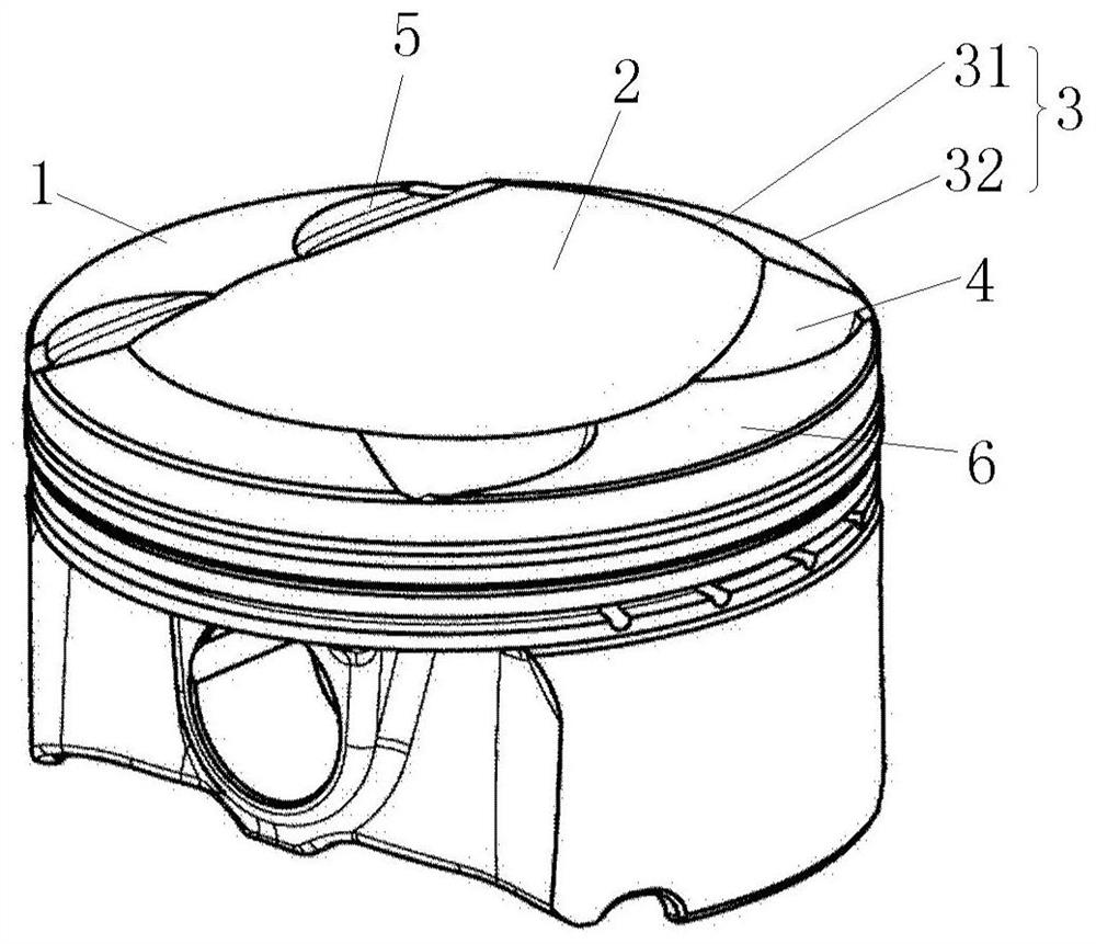
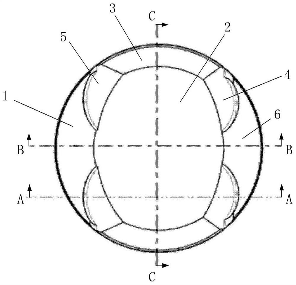
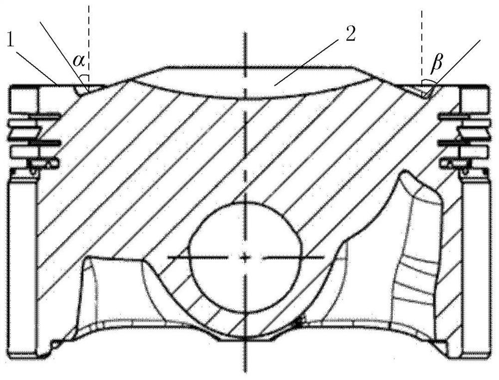
[0065] The disclosure provides an arc-top piston top, an arc-top piston and a combustion chamber. The arc-top piston top includes: an arc-shaped concave area and two conical convex areas. The arc-shaped pit area is a bowl-shaped pit located at the center of the top of the arc-top piston; the height of the first end of the conical raised area is higher than that of the second end of the conical raised area, One end is in contact with the outer edge of the arc-shaped pit area, and the second end of the tapered raised area extends to the edge of the top of the arc-top piston; the two tapered raised areas are respectively located on the front side of the arc-shaped pit area and The rear side, and the two conical convex areas are symmetrically arranged relative to the arc-shaped concave area. The arc-top piston top can be applied to engines with large bores and high compression ratios, which can increase the airflow velocity in the intake stroke of the engine to a large extent, inc...


PUM

PropertyMeasurementUnit
Radiusaaaaaaaaaa

Abstract

The invention provides an arc-top piston top, an arc-top piston and a combustion chamber. The arc-top piston top comprises an arc-shaped pit area and two conical surface protruding area; the arc-shaped pit area is a bowl-shaped pit and is located in the center of the arc-top piston top; the height of the first end of each conical surface protruding area is larger than that of the second end of each conical surface protruding area, the first ends of the conical surface protruding areas make contact with the outer edge of the arc-shaped pit area, and the second ends of the conical surface protruding areas extend to the edge of the arc-top piston top; the two conical surface protruding areas are located on the front side and the rear side of the arc-shaped pit area respectively, and the two conical surface protruding areas are symmetrically arranged relative to the arc-shaped pit area. The arc-top piston top can be applied to a large-cylinder-diameter and high-compression-ratio engine, the airflow movement speed in the air inlet stroke of the engine can be increased to a large extent, the compression stroke and the turbulence energy at the tail end are improved, and the knocking phenomenon of the large-cylinder-diameter and high-compression-ratio engine in the related technology is effectively avoided.

Description

technical field [0001] The disclosure relates to the field of engines, in particular to an arc-top piston top, an arc-top piston and a combustion chamber. Background technique [0002] The engine is the main emission source of air pollutants, but also an important source of carbon emissions. The average annual oil consumption of engines accounts for more than 60% of my country's total oil consumption, and its carbon dioxide emissions exceed 10% of the country's total carbon emissions. With the continuous advancement of the concept of green development, engines are facing the challenge of increasingly stringent emission and fuel consumption regulations. The development of high thermal efficiency and near-zero emission engines has become the primary goal of the academic and engineering circles. At present, the development of high thermal efficiency gasoline engines mainly relies on technical means such as high compression ratio, external cooling EGR (exhaust gas recirculation)...

Claims


Application Information

Patent Timeline
IPC IPC(8): F02F3/00F02F3/26F01M9/00
CPCF02F3/0015F02F3/26F01M9/00
Inventor 王振刘捷杜建秋孙非李德胜
Owner 天津内燃机研究所(天津摩托车技术中心)
Learn More