Supercharge Your Innovation With Domain-Expert AI Agents!

Out-of-pile collection, split charging and retention system for reactor melts

A technology for melts and reactors, used in reactors, cooling devices, emergency protection devices, etc., can solve the problems of large disputes in the estimation of heat flux density, and it is not suitable for high-power reactor types, so as to shorten the cooling time and occupy limited space. , the effect of high resource utilization

Pending Publication Date: 2021-09-17
CHINA NUCLEAR POWER ENG CO LTD
View PDF5 Cites 0 Cited by
  • Summary
  • Abstract
  • Description
  • Claims
  • Application Information

AI Technical Summary

Problems solved by technology

At present, under severe accidents, the cooling and retention strategies of the core melt can be mainly divided into two types: 1) The cooling and retention of the melt in the pressure vessel (IVR), this technology first appeared in the Loviisa VVER-440 power station in Finland , and have been applied in the design of AP600, AP1000, APR1400, CAP1400 (1400MWe pressurized water reactor designed by State Nuclear Power Technology Co., Ltd.) and ACP1000 (1000MWe pressurized water reactor jointly developed and designed by China National Nuclear Corporation and China General Nuclear Power Group), Due to the controversial estimation of the heat flux density of the core melt loaded on the inner wall of the RPV, the current international mainstream opinion believes that the IVR technology is not suitable for larger power reactors, such as reactors above 1000MWe; 2) The melt outside the pressure vessel Cooling and Retention (EVR), which is used in the Russian-designed VVER-1000 model and the European Advanced Pressurized Water Reactor EPR model designed by the French ANP

Method used


Image

  • Out-of-pile collection, split charging and retention system for reactor melts
  • Out-of-pile collection, split charging and retention system for reactor melts
  • Out-of-pile collection, split charging and retention system for reactor melts

Examples


Embodiment Construction

[0032] Embodiments of the present invention are introduced below in conjunction with accompanying drawings:

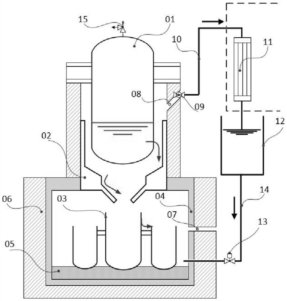
[0033] like figure 1 As shown, the present invention provides a system for collecting, distributing and detaining reactor melt outside the reactor, including a melt collecting device 02, a multi-crucible dispersing and detaining device 03 and a cooling circuit.

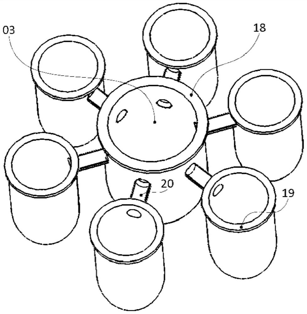
[0034] In order to better collect the molten material that may splash in all directions after the accident, the molten material collection device 02 is installed on the vertical support inner wall of the pressure vessel 01, including the inclined surface and the shroud that are opposite to the lower head of the pressure vessel 01. Said shroud draws in toward the center. like figure 2 As shown, the melt collection device 02 has a two-layer structure, including a lower heat insulation layer 17 and a surface lubricating layer 16; the surface lubricating layer 16 is a hematite layer, which can ensure the smooth...


PUM

PropertyMeasurementUnit
Slopeaaaaaaaaaa

Abstract

The invention discloses an out-of-pile collection, split charging and retention system for reactor melts. The system comprises a melt collection device, a multi-crucible dispersion and retention device and a cooling loop, wherein the melt collecting device is arranged on the vertical supporting inner wall of the pressure vessel and comprises an inclined face and a surrounding plate, and the surrounding plate is folded towards the center. The melt collecting device is of a two-layer structure and comprises a lower heat insulation layer and a surface lubricating layer. The multi-crucible dispersion retention device is arranged at the bottom of a reactor pit and comprises a central main crucible and a plurality of auxiliary crucibles, the central main crucible and the auxiliary crucible are connected through a pore passage penetrating piece; the opening of the central main crucible faces the opening of the coaming; and the cooling loop is connected with the reactor pit so as to cool the multi-crucible dispersion retention device in the reactor pit. The system has the beneficial effects that by adopting the design of melt collection and early-stage lubrication, the amount of the melt is concentrated, and the melt is controllably transferred; besides, the main crucible and the auxiliary crucible are communicated, so that split charging is effectively achieved, the heat exchange area is increased, and the cooling time is shortened.

Description

technical field [0001] The invention belongs to the field of nuclear industry, and in particular relates to a system for collecting, distributing and retaining reactor melt outside the reactor. Background technique [0002] At present, dozens of large-scale second-generation improved nuclear power plants are under construction and in operation in my country, but most of them have not been equipped with effective external melt retention systems. After the Fukushima accident in Japan, the safety of nuclear power plants, especially the prevention and mitigation of severe accidents, is more urgent. At present, under severe accidents, the cooling and retention strategies of the core melt can be mainly divided into two types: 1) The cooling and retention of the melt in the pressure vessel (IVR), this technology first appeared in the Loviisa VVER-440 power station in Finland , and have been applied in the design of AP600, AP1000, APR1400, CAP1400 (1400MWe pressurized water reactor...

Claims


Application Information

Patent Timeline
IPC IPC(8): G21C9/016G21C15/18
CPCG21C9/016G21C15/18Y02E30/30
Inventor 张丽元一单马卫民郭强韩旭李炜曾骁全峰阳郭勇朱光煜梁洋洋裴杰龚耀鹏
Owner CHINA NUCLEAR POWER ENG CO LTD
Features
  • R&D
  • Intellectual Property
  • Life Sciences
  • Materials
  • Tech Scout
  • Unparalleled Data Quality
  • Higher Quality Content
  • 60% Fewer Hallucinations
Learn More