
Overground dry distillation process capable of treating small-particle raw material self-heating type oil shale

A technology of oil shale and small particles, which is applied in the field of self-heating oil shale aboveground carbonization process that can handle small particle raw materials, and can solve the problems of reduced resource utilization, resource waste, and huge oil recovery system, and achieve resource utilization Improved effect

Pending Publication Date: 2021-09-21
郭洪范 +1
View PDF5 Cites 1 Cited by
  • Summary
  • Abstract
  • Description
  • Claims
  • Application Information

AI Technical Summary

Problems solved by technology

[0005] The gas heat carrier process itself has a huge defect: the carbonization furnace can only process large-grained oil shale with a particle size of 12mm or more
When small particles of oil shale are used as raw materials for dry distillation, the pores between oil shale particles are very small due to the close accumulation of small particles of oil shale particles, and the gas heat carrier process uses a large amount of high-temperature heat carrier, so the thermal The carrier gas cannot pass through the oil shale particles smoothly, which makes dry distillation impossible. Therefore, most of the small oil shale particles below 12mm are discarded, reducing the utilization rate of resources by 25%-40%, resulting in a serious waste of resources
Extensive use of high-temperature heat-carrying gas also causes many other problems. For example, not only the secondary cracking and coking of oil and gas reduces the oil recovery rate, but also the oil and gas mixed in a large amount of heat-carrying gas also leads to a large amount of gas at the outlet of the carbonization furnace, and the oil recovery system Huge and difficult to recover oil condensation, etc.

Method used


Image

  • Overground dry distillation process capable of treating small-particle raw material self-heating type oil shale
  • Overground dry distillation process capable of treating small-particle raw material self-heating type oil shale

Examples


Embodiment Construction

[0026] In order to make the object, technical solution and advantages of the present invention more clear, the present invention will be further described in detail below in conjunction with the examples. The specific embodiments described here are only used to explain the present invention, not to limit the invention.

[0027] Since the principle of the traditional gas heat carrier process is to feed high-temperature gas into the oil shale in the carbonization furnace, the high-temperature gas is used to heat the oil shale by directly mixing with the oil shale material, that is to say, the high-temperature heat transfer is carried out through heat transfer. The heat of the gas is transferred to the oil shale to raise the temperature of the oil shale. Since the oil shale needs to be heated to above 500°C, a large amount of heat carrier gas needs to be used. The small grains of oil shale below 12mm are closely packed so that the gaps between the grains are very small, and a lar...


PUM


Abstract

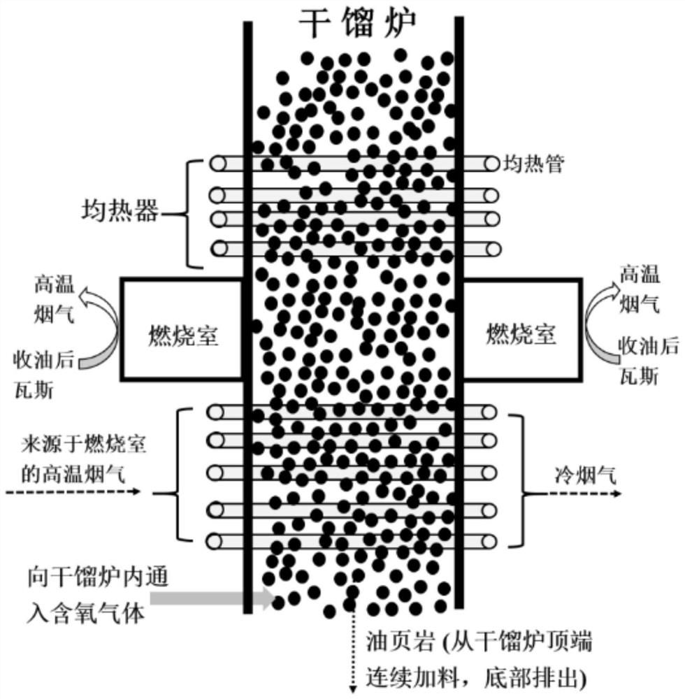
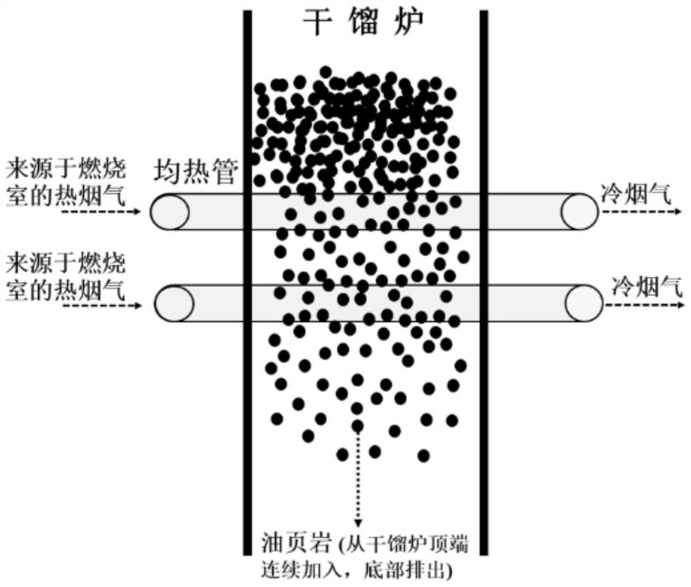
The invention discloses an overground dry distillation process capable of treating small-particle raw materials self-heating type oil shale. The process comprises the following steps: utilizing low-temperature partial oxidation reaction generated by oil shale for in-situ heat release; and meanwhile, arranging a plurality of combustion chambers and soaking devices around the dry distillation furnace, and enabling high-temperature flue gas generated by combustion in the combustion chambers to radiate and conduct heat to the oil shale to be subjected to dry distillation through the devices, namely, the flue gas is not directly mixed with dry distillation materials and oil gas. In addition, the oil shale particles collide with the metal soaking pipe penetrating through the oil shale material layer in the descending process in the dry distillation furnace, so that gaps among the oil shale particles are enlarged. The method improves the utilization rate of resources, and has the advantages of high energy efficiency and resource utilization rate, water saving, small environmental influence, simplified process, no high-temperature heat carrier and relatively mild reaction conditions.

Description

technical field [0001] The invention relates to the technical field of above-ground oil shale dry distillation, in particular to a self-heating above-ground oil shale dry distillation process capable of processing small particle raw materials. Background technique [0002] Oil shale is a kind of sedimentary rock containing combustible organic matter and high ash content. The organic matter contained in it can be obtained by dry distillation to obtain shale oil similar to crude oil. my country's oil shale reserves are quite rich, according to the survey of the Ministry of Land and Resources in 2006, it was 729.9 billion tons. On the other hand, my country's dependence on foreign oil has exceeded 70%, and there is a huge risk in crude oil supply. Therefore, oil shale can be used as an important petroleum supplementary energy source, and its development has attracted more and more attention. [0003] Because oil shale organic matter (mainly kerogen with solid macromolecular n...

Claims


Application Information

Patent Timeline
Patent Type & Authority Applications(China)
IPC IPC(8): C10B53/06C10G1/00
CPCC10B53/06C10G1/00
Inventor 郭洪范刘云义王卓王志远窦泽伟熊莉佳
Owner 郭洪范
Learn More