Storage tank for chemical production

A technology for chemical production and storage tanks, which is applied in the direction of tank trucks, final product manufacturing, and reaction engines. It can solve the problems of safe storage of vinyl acetate, corrosion of the outer surface of storage tanks, and large consumption, and achieve the reduction of algae and other microorganisms. The effect of breeding, cleaning and prolonging, ensuring safety

Inactive Publication Date: 2021-09-21
吕庆霖
View PDF4 Cites 0 Cited by
  • Summary
  • Abstract
  • Description
  • Claims
  • Application Information

AI Technical Summary

Problems solved by technology

[0002] In the process of storing vinyl acetate after production, it needs to be stored at a temperature below 30 degrees Celsius, and due to the large volume of the storage tank, it is often placed outdoors, and the storage tank placed outdoors is directly exposed to sunlight. In high temperature weather, it is easy to make the temperature of the storage tank too high, which will seriously affect the safe storage of vinyl acetate. In order to solve this problem, the storage tank often needs to be considered in terms of insulation and heat preservation during the design process. At the same time, some other cooling measures will be adopted, such as spraying water on the outer surface of the tank to cool down, while the traditional water spraying mostly uses industrial water, which not only consumes a lot, but also uses industrial water for a long time to damage the outer surface of the storage tank. At the same time, if industrial water is used for direct spraying, the waste water after spraying is often directly processed by sewage treatment pipelines, and cannot be used elsewhere, resulting in waste, which highlights the shortcomings of traditional storage tanks

Method used


Image

  • Storage tank for chemical production
  • Storage tank for chemical production
  • Storage tank for chemical production

Examples


Embodiment Construction

[0019] The present invention will be further elaborated below in conjunction with the accompanying drawings and specific embodiments.

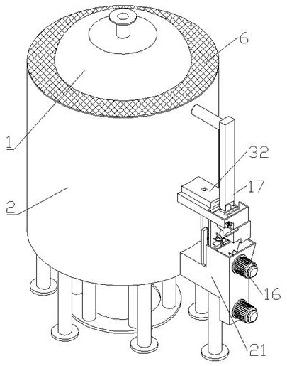
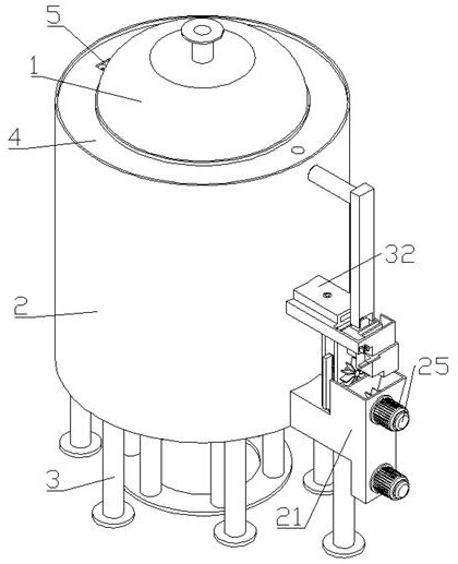
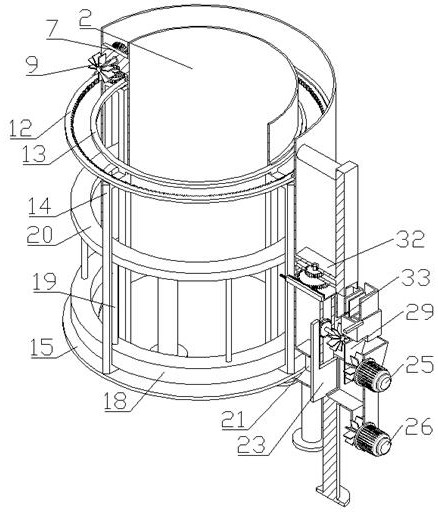
[0020] Such as Figure 1-8 As shown, a storage tank for chemical production includes a storage tank body 1, a cooling water tank 2, a support leg 3, a collection guide ring 4, a collection guide port 5, an annular filter screen 6, a mounting seat 7, and a large bevel gear with shaft 8 , upper toggle paddle 9, small belt shaft bevel gear 10, No. 1 gear 11, ring gear 12, upper support ring 13, hollow scraper 14, lower support ring 15, power generation part 16, control part 17, the storage tank There is a vertical cooling water tank 2 socketed on the outer wall of the body 1. A plurality of vertical support legs 3 are fixed at the bottom of the cooling water tank 2. A horizontal collection guide ring 4 is fixed on the top of the cooling water tank 2. The collection guide There is a vertical collection guide port 5 running through the left part o...


PUM


Abstract

The invention discloses a storage tank for chemical production. The storage tank for chemical production comprises a storage tank body, a cooling water tank, supporting legs, a collection guide ring, a collection guide port, an annular filter screen, a mounting seat, a large bevel gear with a shaft, an upper stirring paddle, a small bevel gear with a shaft, a first gear, a gear ring, an upper support ring, a hollow scraper, a lower support ring, a power generation part and a control part, the vertical cooling water tank is connected to the outer wall of the storage tank body in a sleeving mode, a plurality of vertical supporting legs are fixed to the bottom end of the cooling water tank, the horizontal collection guide ring is fixed to the top of the cooling water tank, the vertical collection guide port penetrates through the left portion of the collection guide ring, and the horizontal annular filter screen is fixed to the top end of the cooling water tank. Rainwater is efficiently utilized, the purpose of water cooling is achieved, meanwhile, the rainwater can be utilized for power generation, the multiple functions of automatic drainage, automatic water storage and automatic cleaning are achieved through the rainwater, and the device is more environmentally friendly and efficient.

Description

technical field [0001] The invention relates to the field of chemical production, in particular to a storage tank for chemical production. Background technique [0002] In the process of storing vinyl acetate after production, it needs to be stored at a temperature below 30 degrees Celsius, and due to the large volume of the storage tank, it is often placed outdoors, and the storage tank placed outdoors is directly exposed to sunlight. In high temperature weather, it is easy to make the temperature of the storage tank too high, which will seriously affect the safe storage of vinyl acetate. In order to solve this problem, the storage tank often needs to be considered in terms of insulation and heat preservation during the design process. At the same time, some other cooling measures will be adopted, such as spraying water on the outer surface of the tank to cool down, while the traditional water spraying mostly uses industrial water, which not only consumes a lot, but also us...

Claims


Application Information

Patent Timeline
IPC IPC(8): F03B3/12F03B3/18F03B11/02F03B13/00B65D88/74B65D90/00B65D90/02B65D90/26
CPCF03B13/00F03B11/02F03B3/18F03B3/12B65D88/744B65D90/028B65D90/00B65D90/0093B65D90/26Y02P70/50Y02E10/20
Inventor 吕庆霖程东
Owner 吕庆霖
Why Eureka
Try Eureka