Formation consistency control method for multiple AUVs under directed switching topology
A control method and consistent technology, applied in the direction of non-electric variable control, height or depth control, control/regulation system, etc., can solve the problems of poor robustness and stability, and achieve good stability, robustness, and speed The effect of fast and improved convergence speed
- Summary
- Abstract
- Description
- Claims
- Application Information
AI Technical Summary
Problems solved by technology
Method used
Image


Examples
specific Embodiment approach 1
[0031] The specific embodiment one, the multi-AUV formation consistency control method under the directed switching topology described in the present embodiment, the method specifically includes the following steps:
[0032] Step 1. Define a directed graph for describing the communication topology relationship between multiple AUVs;
[0033] Step 2. Based on the feedback linearization method, the kinematic equation and dynamic equation of the AUV are linearized into a feedback linearization dynamic model in the form of a second-order integral;
[0034] Step 3, using the communication topology relationship between AUVs represented by the directed graph and the feedback linearization dynamic model of the second-order integral form, design a multi-AUV formation consistency controller under the directed switching topology;
[0035] Step 4. Based on the controller in step 3, the closed-loop control form of each AUV is obtained.
specific Embodiment approach 2
[0036] Specific implementation mode two, the difference between this implementation mode and specific implementation mode one is: the specific process of said step one is:
[0037] Take each AUV as a vertex of a directed graph, and the directed graph is marked as G=(V,ε,C), where V represents the set of all vertices, and V={v 1 ,v 2 ,...,v n}, n is the number of AUVs in the formation, (v i ,v j )∈ε, ε represents the set of edges between vertices, that is, the set of communication chains of each AUV member, (v i ,v j ) represented by the vertex v i and v j The directed edge formed by the vertex v j Receive vertex v i information, v i is called the parent vertex of the edge, v j Called the sub-vertex of the edge, C is the adjacency matrix;
[0038] The adjacency matrix C satisfies: for If i=j, then c ij =0, if i≠j and there is a directed edge in the set ε (v i ,v j ), then c ij = 1, otherwise c ij =0.
[0039] The in-degree matrix of the directed graph D=dia...
specific Embodiment approach 3
[0041] Specific embodiment 3. The difference between this embodiment and one of specific embodiments 1 or 2 is that the kinematic equation of the AUV is:
[0042]
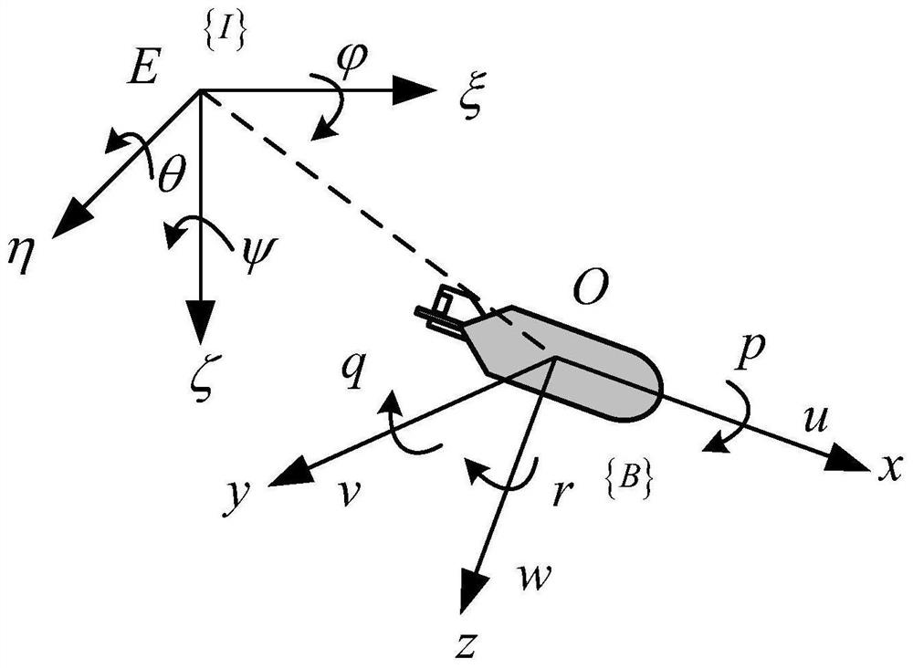
[0043] In the formula, is the first derivative of η, Indicates the position state and the Euler angle state, ξ 0 is the north coordinate of AUV, η 0 is the east coordinate of AUV, ζ 0 is the longitudinal coordinate of AUV, θ is the pitch angle of AUV, ψ is the heading angle of AUV, represents the field of real numbers, Indicates the state of velocity, u 0 is the northward velocity of the AUV, v 0 is the eastward velocity of the AUV, w 0 is the longitudinal velocity of the AUV, q is the pitch angular velocity of the AUV, r is the heading angular velocity of the AUV, and J(η) is the Jacobian matrix of the AUV from the moving coordinate system to the fixed coordinate system.
[0044] Other steps and parameters are the same as those in Embodiment 1 or Embodiment 2.
PUM
 Abstract
Description
Claims
Application Information
 - R&D
- Intellectual Property
- Life Sciences
- Materials
- Tech Scout
- Unparalleled Data Quality
- Higher Quality Content
- 60% Fewer Hallucinations
Browse by: Latest US Patents, China's latest patents, Technical Efficacy Thesaurus, Application Domain, Technology Topic, Popular Technical Reports.
© 2025 PatSnap. All rights reserved.Legal|Privacy policy|Modern Slavery Act Transparency Statement|Sitemap|About US| Contact US: help@patsnap.com