Parallel IGBT dynamic current sharing buffer circuit

A snubber circuit and current snubber technology, applied in the field of parallel IGBT dynamic current sharing snubber circuit, can solve the problems of shortening the structural life of the IGBT parallel circuit, prolonging the current tailing time, increasing the switching stress, etc. The effect of polar circulation, shortening the current tailing time, and increasing the equivalent resistance value

Active Publication Date: 2021-09-24
CENT SOUTH UNIV
View PDF5 Cites 1 Cited by
  • Summary
  • Abstract
  • Description
  • Claims
  • Application Information

AI Technical Summary

Problems solved by technology

Common methods of current sharing at the drive end include gate resistance compensation (for example: M.Sasaki, H.Nishio, A.Shorten and W.T.Ng, "Current balancing control for parallel connected IGBTs using programmable gate driver output resistance," 2013 25th International Symposium on Power Semiconductor Devices&IC's (ISPSD), Kanazawa, Japan, 2013, pp.65-68.) and active gate control method (for example: D.Bortis, J.Biela and J.W.Kolar,"Active Gate Control for Current Balancing of Parallel- Connected IGBT Modules in Solid-State Modulators,"in IEEE Transactions on Plasma Science,vol.36,no.5,pp.2632-2637,Oct.2008.), etc. These methods are not only complicated, but also prone to gate circulation
The power end current sharing technology is mainly realized based on the snubber circuit of series inductors. However, when the single-inductance snubber circuit is applied, since the inductor has no freewheeling channel when the IGBT is disconnected, the tailing time of the current is prolonged, and the inductance is reversed. The voltage increases the switching stress, resulting in a shortened life of the IGBT parallel circuit structure

Method used


Image

  • Parallel IGBT dynamic current sharing buffer circuit
  • Parallel IGBT dynamic current sharing buffer circuit
  • Parallel IGBT dynamic current sharing buffer circuit

Examples


Embodiment Construction

[0024] The present invention will be clearly and completely described below in conjunction with the accompanying drawings and embodiments, and the technical problems and beneficial effects solved by the technical solutions of the present invention are also described. It should be pointed out that the described embodiments are only intended to facilitate the implementation of the present invention understood without any limitation.

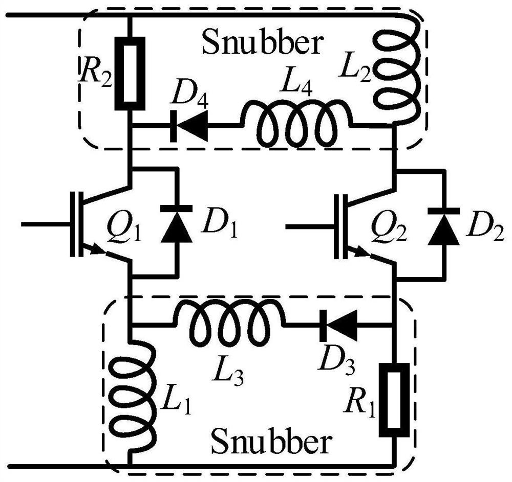
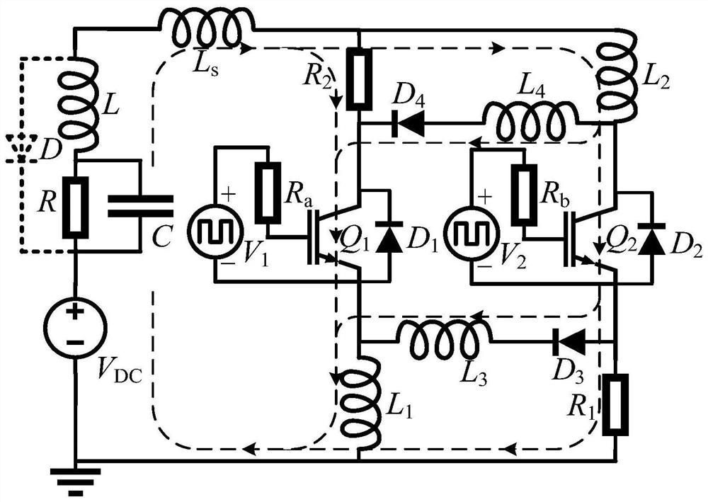
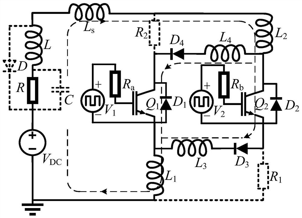
[0025] The parallel IGBT dynamic current equalization buffer circuit designed by the present invention is suitable for the dual parallel IGBT circuits in general power electronic hardware, so as to automatically suppress the circulating current in the circuit, so as to play the role of current equalization. The IGBT parallel circuit is used as an example, and it should be pointed out that the snubber circuit can also be applied to a P-type IGBT parallel circuit, and its complementary symmetrical structure that realizes the same working mode should a...


PUM


Abstract

The invention discloses a parallel IGBT dynamic current sharing buffer circuit, which comprises two IGBT tubes Q1 and Q2 and a buffer circuit part, and is characterized in that the buffer circuit part comprises buffer inductors L1 and L2, buffer resistors R1 and R2, interconnection diodes D3 and D4 and interconnection inductors L3 and L4. According to the dynamic current sharing buffer circuit, an upper buffer circuit and a lower buffer circuit which are composed of R2, D4, L4, L2, L1, L3, D3 and R1 are organically matched, the dynamic current sharing function of parallel IGBTs can be automatically achieved, safe and stable operation of each IGBT is guaranteed, meanwhile, the current trailing time can be shortened, the problems of transient opening oscillation and gate pole ring current can be avoided, and the circuit is simple in structure, and the software and hardware cost is low.

Description

technical field [0001] The invention belongs to the technical field of power electronic devices, and more specifically relates to a parallel IGBT dynamic current sharing buffer circuit. Background technique [0002] In the prior art, IGBT is a high-power power electronic switching device. Whether it is limited by the insufficient current capacity of a single module or the cost advantage of the parallel connection scheme, more and more applications require the IGBT module parallel connection scheme. Due to the inconsistency of its own parameters and external parameters, there may be differences in the current of parallel IGBTs. In order to give full play to the advantages of parallel connection, the current sharing effect is particularly important. Otherwise, severe current imbalance will cause a certain module to bear excessive current, thereby limiting the overall output capability of the parallel connection module and failing to achieve the expected parallel connection eff...

Claims


Application Information

Patent Timeline
Patent Type & Authority Applications(China)
IPC IPC(8): H02M1/34
CPCH02M1/34
Inventor 邹润民王嘉智汪运游傲
Owner CENT SOUTH UNIV
Why Eureka
Try Eureka