
Precoated sand mold for casting stainless steel thin-walled workpiece

A technology of thin-walled parts and coated sand, applied in the direction of manufacturing tools, casting molding equipment, casting molds, etc., can solve the problem of reducing the use efficiency of devices, inconvenient cleaning for users, collecting coated sand, and increasing production costs for users, etc. problem, to achieve the effect of improving production efficiency

Active Publication Date: 2021-10-01
池州鸿博通用机械制造有限公司
View PDF10 Cites 1 Cited by
  • Summary
  • Abstract
  • Description
  • Claims
  • Application Information

AI Technical Summary

Problems solved by technology

[0003] In the process of realizing the present invention, it is found that at least the following problems in the prior art have not been solved: 1. When injecting liquid metal into the coated sand mold of casting stainless steel thin wall, it is necessary to clamp the coated sand molds of different sizes However, the existing device is cumbersome to operate and is not convenient for the user to operate, thereby reducing the work efficiency of the user;
[0004] 2. After using the traditional device for holding the coated sand mold, some coated sand will fall off the surface of the device, and the user needs to manually clean the surface of the device in order not to affect the operation of the device, which increases the labor intensity of the user , and it is not convenient for the user to clean and collect the coated sand, which increases the user's production cost and reduces the use efficiency of the device

Method used


Image

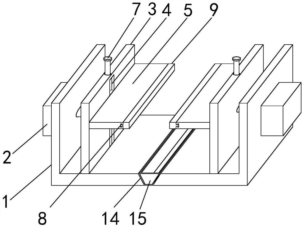
  • Precoated sand mold for casting stainless steel thin-walled workpiece
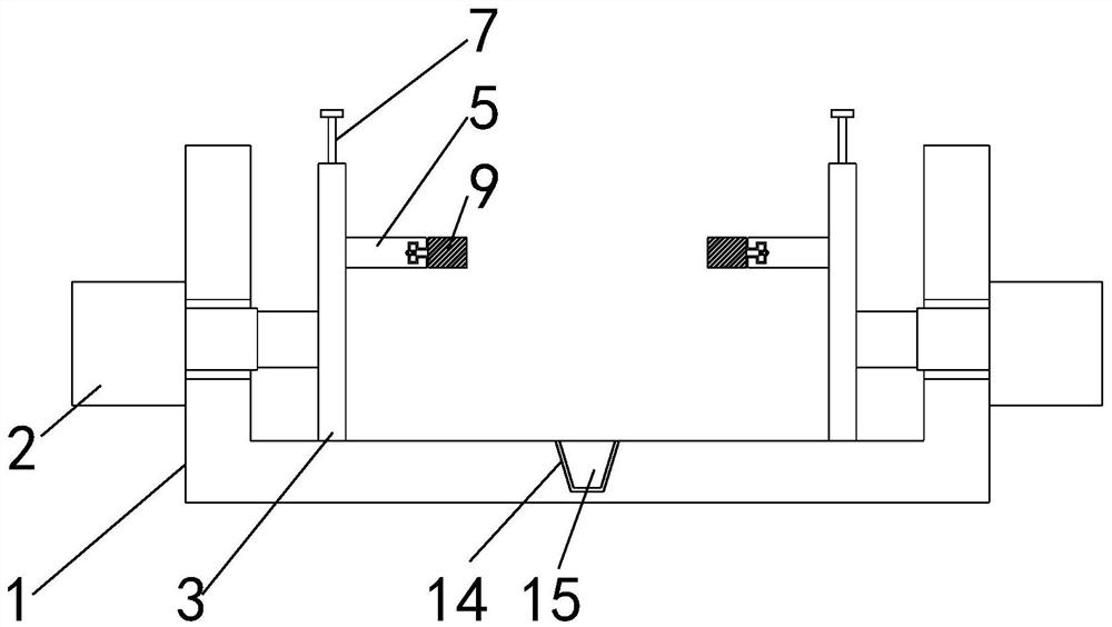
  • Precoated sand mold for casting stainless steel thin-walled workpiece
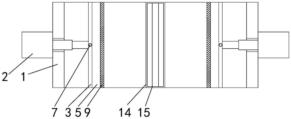
  • Precoated sand mold for casting stainless steel thin-walled workpiece

Examples


Embodiment Construction

[0032] The technical solutions of the present invention will be clearly and completely described below in conjunction with the embodiments. Obviously, the described embodiments are part of the embodiments of the present invention, but not all of them. Based on the embodiments of the present invention, all other embodiments obtained by persons of ordinary skill in the art without making creative efforts belong to the protection scope of the present invention.

[0033] In describing the present invention, it is to be understood that the terms "center", "longitudinal", "transverse", "length", "width", "thickness", "upper", "lower", "front", " Back", "Left", "Right", "Vertical", "Horizontal", "Top", "Bottom", "Inner", "Outer", "Clockwise", "Counterclockwise", etc. or The positional relationship is based on the orientation or positional relationship shown in the drawings, which is only for the convenience of describing the present invention and simplifying the description, rather t...


PUM


Abstract

The invention relates to the technical field of precoated sand molds, in particular to a precoated sand mold for casting a stainless steel thin-walled workpiece. The mold comprises a supporting plate, the supporting plate is of a U-shaped structure, an air cylinder is arranged on the outer surface of one side of the supporting plate, and a movable plate is fixedly connected to the outer surface of the other side of the air cylinder; and a movable groove is formed in the center of the outer surface of one side of the movable plate, a clamping plate is slidably connected to the interior of the movable groove, a cleaning brush is arranged on the outer surface of the other side of the clamping plate, a connecting groove is formed in the center of the outer surface of the upper end of the supporting plate, and a storage groove is clamped to the interior of the connecting groove. According to the mold, due to the fact that the movable groove and the T-shaped structure are matched in structure, and a bearing is arranged inside the clamping plate, a user can conveniently clamp and fix the precoated sand mold for casting the stainless steel thin-walled workpiece, and after casting of the stainless steel thin-walled workpiece is completed, the user can conveniently clean and collect fallen precoated sand, the production cost of the user is reduced, and the use efficiency of the device is improved.

Description

technical field [0001] The invention relates to the technical field of coated sand molds, in particular to a coated sand mold for casting stainless steel thin-walled parts. Background technique [0002] 1. Coated sand (coated sand), the surface of the sand grains is covered with a layer of solid resin film before molding sand or core sand, there are two coating processes: cold method and hot method: cold method dissolves the resin with ethanol, and Add urotropine during the sand mixing process to coat the two on the surface of the sand, and volatilize the ethanol to obtain coated sand; preheat the sand to a certain temperature by thermal method, add resin to melt it, and stir to coat the resin on the sand On the surface, add urotropine aqueous solution and lubricant, cool, crush, and sieve to obtain coated sand, which is used for steel castings and iron castings. [0003] In the process of realizing the present invention, it is found that at least the following problems in ...

Claims


Application Information

Patent Timeline
Patent Type & Authority Applications(China)
IPC IPC(8): B22C9/02B22C23/00B08B1/00
CPCB22C9/02B22C23/00B08B1/12
Inventor 杨柴曹桂荣
Owner 池州鸿博通用机械制造有限公司
Learn More