Industrial circulating cooling water system and energy-saving operation method thereof

A technology for circulating cooling water and industry, which is applied in the chemical industry, water shower coolers, cooling fluid circulation devices, etc. It can solve the problems of less consideration of climate characteristics and weather changes, insufficient cooling capacity of cooling towers, and high operating energy consumption.

Active Publication Date: 2021-10-01
CHANGSHA KAIYI ENERGY SAVING TECH
View PDF5 Cites 0 Cited by
  • Summary
  • Abstract
  • Description
  • Claims
  • Application Information

AI Technical Summary

Problems solved by technology

The current industrial circulating cooling water system mainly faces two technical problems: on the one hand, the energy consumption of dynamic equipment such as fans and pumps in the system is relatively high, and it is necessary to save energy as much as possible; The cooling capacity of the cooling tower in the water system is insufficient, which may not be able to meet the needs of water temperature control
At present, there are many reports on the energy-saving transformation of industrial circulating cooling water systems in the known technology, but less consideration is given to the specific local climate characteristics and weather change factors.

Method used


Image

  • Industrial circulating cooling water system and energy-saving operation method thereof

Examples


Embodiment

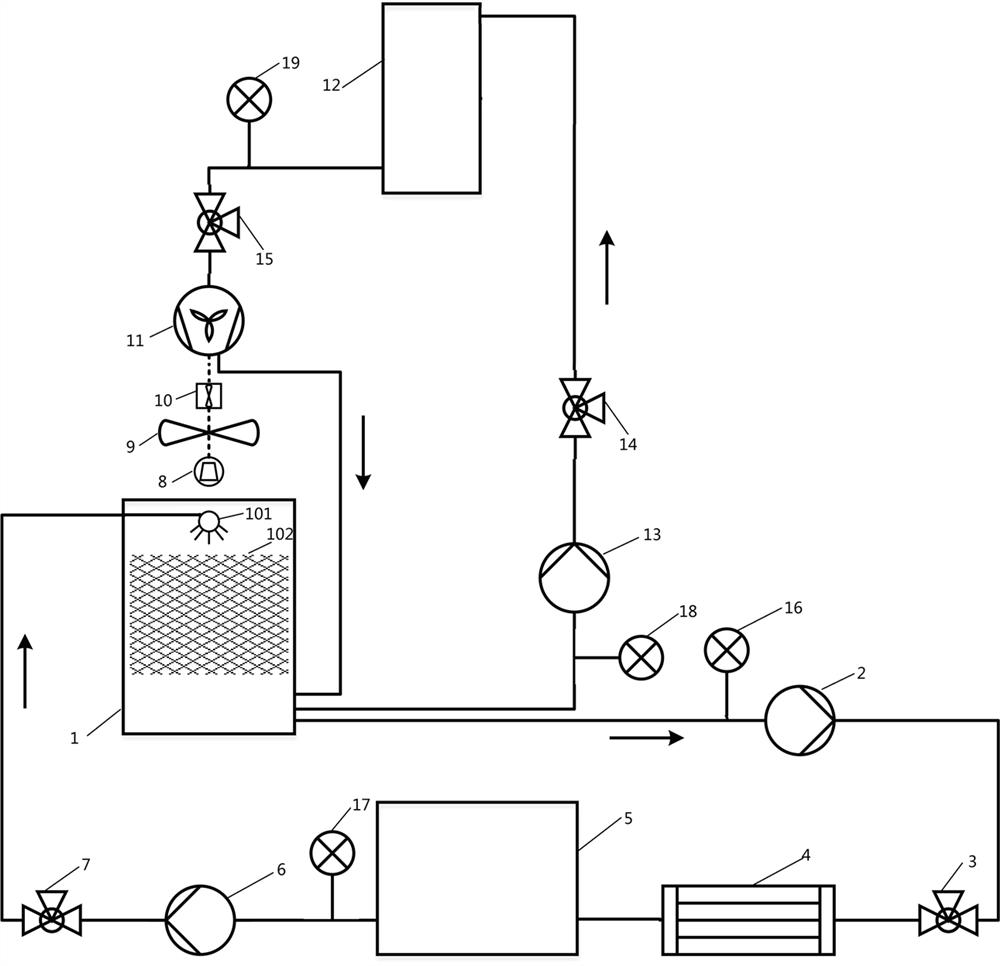
[0028] A certain ironworks is located in a certain place in Northwest China. The area is mountainous, and the temperature difference between day and night is large all the year round, and the area implements relatively cheap peak and valley electricity prices around midnight at night. The ironmaking plant uses a circulating cooling water system to cool certain process equipment, please refer to the attached figure 1 . The maximum allowable flow value Q of the circulating cooling water system m and design flow value Q r 600m respectively 3 / h and 500m 3 / h, the rated speed and rated power of the fan 9 are 750r / min and 10kW respectively, and the suitable water temperature range of the circulating cooling water flowing into the terminal process equipment 4 during its operation is 18°C ​​to 26°C. In this embodiment, the operating time period of the early morning mode is set from 1 hour before zero time to 2 hours after zero time (that is, from 23:00 to 2:00 the next day), and ...


PUM


Abstract

The invention discloses an industrial circulating cooling water system and an energy-saving operation method thereof. The system comprises a cooling tower, a first water pump, a first valve, tail end process equipment, a low-level water tank, a second water pump and a second valve which are sequentially connected in series through a pipeline closed loop, a water distributor with one end communicating with a water inlet pipeline of the cooling tower is arranged at the top in the cooling tower, a filler is arranged below the water distributor, a fan is arranged over the cooling tower, the two ends of a rotating shaft of the fan are connected to a servo motor and a water turbine correspondingly, the high-level water tank is arranged above the cooling tower, the bottom of the cooling tower sequentially communicates with a third water pump, a third valve and the top of the high-level water tank through pipelines, the bottom of the high-level water tank communicates with a water inlet pipeline of the water turbine through a pipeline, a fourth valve is arranged on a communicating pipeline between the high-level water tank and the water turbine, and an outlet of the water turbine communicates with the bottom of the cooling tower through a pipeline. The industrial circulating cooling water system and the energy-saving operation method thereof are stable, reliable, simple and convenient to operate and good in energy-saving effect, and local weather and geographical conditions can be fully considered.

Description

technical field [0001] The invention belongs to the technical field of industrial circulating cooling, and in particular relates to an industrial circulating cooling water system and an energy-saving operation method thereof. Background technique [0002] Industrial circulating cooling water systems widely exist in various fields of process industries such as metallurgy and chemical industry, and are used to cool process equipment and materials. The current industrial circulating cooling water system mainly faces two technical problems: on the one hand, the energy consumption of dynamic equipment such as fans and pumps in the system is relatively high, and it is necessary to save energy as much as possible; The cooling tower in the water system has insufficient cooling capacity and may not be able to meet the water temperature control needs. At present, there are many reports on the energy-saving transformation of industrial circulating cooling water systems in the known te...

Claims


Application Information

Patent Timeline
IPC IPC(8): F25D17/02F25D29/00F28C1/00
CPCF25D17/02F25D29/005F28C1/00F28C2001/006Y02P20/10
Inventor 刘冬桂江旭蒋敦军周京武康秀峰熊军
Owner CHANGSHA KAIYI ENERGY SAVING TECH
Why Eureka
Try Eureka