Check patentability & draft patents in minutes with Patsnap Eureka AI!

Coupling method for improving tracking error of optical device with refrigeration function

A tracking error and optical device technology, applied in the coupling of optical waveguides, optical components, light guides, etc., can solve the problems of large performance differences, increased power consumption, and large differences in product power consumption, achieving small performance differences and improved tracking Good effect of error and product consistency

Active Publication Date: 2021-10-01
XGIGA COMM TECH
View PDF4 Cites 0 Cited by
  • Summary
  • Abstract
  • Description
  • Claims
  • Application Information

AI Technical Summary

Problems solved by technology

The difference in optical power between high and low temperature and normal temperature is large, that is, the difference in TE
[0008] TOSA (light transmitting module) packaged in coaxial or BOX of the same type, if the laser and lens are not on the same temperature control surface, the thermal Expansion and contraction will lead to large changes in optical power at high and low temperatures, that is, TE is poor, even reaching 2-3dB, and it has been difficult to improve. The general agreement requires TE to be less than 1dB. Now the common method is to compensate the laser working current at high and low temperatures , for example, the optical power decreases at high temperature, and the laser operating current should be reduced to maintain the optical power at room temperature.
When the optical power increases at low temperature, reduce the working current of the laser to maintain the optical power level at room temperature. Doing so will cause cracking of the high and low temperature performance of the product. At the same time, increasing the working current will increase power consumption, and reducing the working current will cause the product to fail best working point
The performance of the final product varies greatly under high temperature, low temperature, and normal temperature, and the power consumption of the product varies greatly

Method used


Image

  • Coupling method for improving tracking error of optical device with refrigeration function
  • Coupling method for improving tracking error of optical device with refrigeration function
  • Coupling method for improving tracking error of optical device with refrigeration function

Examples


Embodiment Construction

[0029] The present invention will be described in further detail below in conjunction with the accompanying drawings and embodiments.

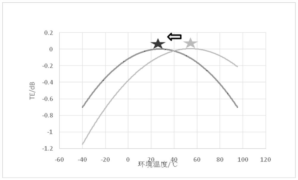
[0030] Such as image 3 As shown, the method of the present invention is used to ameliorate the problem of large TE. The gray line curve indicates that the TE is very poor at low temperature, reaching -1.2dB. It can be seen that the TE at low temperature is much larger than that at high temperature, which means that the focal length changes greatly at high and low temperatures. The purpose of the present invention is to adjust the temperature & TE curve into a black double line curve.

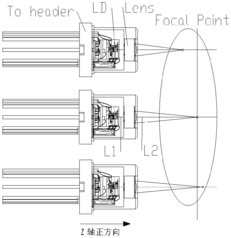
[0031] Through a large number of experiments and optical simulations, it is found that it is necessary to balance the focal length of the optical coupling between the adapter and the TO socket, that is, it is not conventional to couple to the maximum value and then fix it by laser welding, and to make an offset in the Z-axis direction after the maximum couplin...


PUM


Abstract

The invention provides a coupling method for improving tracking errors of an optical device with a refrigeration function, and belongs to the technical field of optical path alignment coupling. The method comprises the following steps: S1, in adapter coupling, coupling optical power to a maximum value; S2, finding the optimal defocusing amount of TE through a defocusing experiment, wherein the TE is a tracking error; S3, adjusting the Z-axis position of the adapter from the lens according to the defocusing amount; and S4, fixing the adapter. The method has the beneficial effects that the tracking error of the refrigerating optical device can be effectively improved, the performance difference at high temperature, low temperature and normal temperature is small, and the product consistency is good.

Description

technical field [0001] The invention relates to an optical path alignment coupling technology, in particular to a coupling method for improving the tracking error of an optical device with cooling. Background technique [0002] Using a typical coaxial optical device with cooling such as figure 1 Shown as an example, the laser diode (laserdiode) 1001 is referred to as LD, including the commonly used electric absorption laser diode (EML), and DFB (Distributed feedback, distributed feedback LD, referred to as DFB), LD chip mount It is called COC (chip on carrier, carrier chip) 1002 on the LD carrier. The COC is mounted on the L-shaped tungsten copper block (CuW for short) 1003, and there is also a monitoring receiver for monitoring the LD optical power attached to the CuW block. Diode (Monitor photodiode, referred to as MPD) 1004, a thermistor (thermistor) 1005 attached to the CuW block is used for temperature feedback, CuW is attached to the electronic cooler (abbreviated as ...

Claims


Application Information

Patent Timeline
Patent Type & Authority Applications(China)
IPC IPC(8): G02B6/42
CPCG02B6/4206G02B6/4225G02B6/4286G02B6/4296
Inventor 朱宁宁黄凯威
Owner XGIGA COMM TECH
Features
  • R&D
  • Intellectual Property
  • Life Sciences
  • Materials
  • Tech Scout
  • Unparalleled Data Quality
  • Higher Quality Content
  • 60% Fewer Hallucinations
Learn More