Film processing device and method

A processing device and film technology, which is applied in the field of film drawing device, can solve the problems of low longitudinal thermal shrinkage rate, heavy load of steel belt, elongation and deformation of steel belt in horizontal pull track, etc., so as to improve longitudinal thermal shrinkage rate and save installation Space, the effect of ensuring the clamping effect

Pending Publication Date: 2021-10-08
HEFEI LUCKY SCI & TECH IND
View PDF0 Cites 0 Cited by
  • Summary
  • Abstract
  • Description
  • Claims
  • Application Information

AI Technical Summary

Problems solved by technology

The first method is the synchronous stretching method, that is, the magnetic levitation chain clip is used for the horizontal zipper clip. When the chain clip is running on the horizontal pull track, each chain clip has a motor that can run independently in the track. Speed ​​operation, so that the clamped film has longitudinal and transverse tension, but the cost of this method is extremely high, the cost is increased by about 100 million yuan, and the longitudinal traction is small, only used in the preparation of films below 12μ, and the structure is complicated, The failure rate is also high; another method is to use the chain clip system with chain shrinkage function. The distance between the chain clip and the chain clip is not fixed. Forcibly shorten the distance between the chain clamp and the chain clamp by about 1cm, so that the film can release the stress in the longitudinal direction, and the film has shrinkage space in the longitudinal direction, so that the longitudinal thermal shrinkage rate can be improved. This method can be used for films below 250μ, but the The system needs an additional cost of 50 million RMB, and because the steel belt of the track is greatly affected by the shrinkage mechanism, the load of the steel belt is heavy, and it is easy to cause serious failures such as elongation, deformation and fracture of the steel belt of the horizontal tension track. The manufacturer recommends that it should be replaced every year The steel belt in the horizontal cooling zone will cost an additional 600,000 per year
[0006] For 99% of the current domestic production lines, the above two methods involve huge investment and a long transformation period, and the cost-effectiveness for only improving the longitudinal thermal shrinkage rate among many properties is relatively low.

Method used


Image

  • Film processing device and method
  • Film processing device and method
  • Film processing device and method

Examples


Embodiment 1

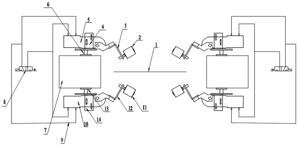
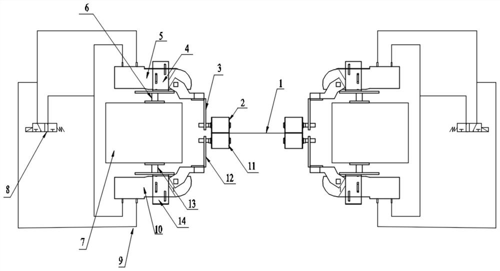
[0041] Depend on figure 2 Given, the film processing device of the present invention comprises a horizontal stretch box and a horizontal stretch unit, the horizontal stretch unit is located in the horizontal stretch box, and the horizontal pull unit includes two chain clip tracks 7 and is installed on the chain clip track 7 The horizontal pull chain 19 of parallel endless rotation on the top; the horizontal pull unit includes: the horizontal pull nip roller unit and the horizontal pull cutter unit arranged in the horizontal pull box; the horizontal pull box includes the N3 area in the horizontal pull box, Cooling Zone 1 and Cooling Zone 2, the N3 Zone, Cooling Zone 1, and Cooling Zone 2 are arranged in sequence along the pulling direction of the film 1; the horizontal stretching nip roller unit includes two sets of nip rollers; the two sets of nip rollers Separately located in the cooling zone 1 and the cooling zone 2; each set of nip rolls can clamp both sides of the film 1 ...

Embodiment 2

[0047] Depend on figure 1 , figure 2 Given, different from Embodiment 1, in order to ensure the safety of personnel and equipment on the production line, the production safety line is provided with a membrane rupture signal, which is connected in parallel with the solenoid valve 8, and the solenoid valve acts immediately in the event of an accidental membrane rupture. In order to realize the timely opening of the nip rollers, the film processing devices all enter the non-working position state, so as to prevent the film from causing harm to personnel and equipment on the line.

Embodiment 3

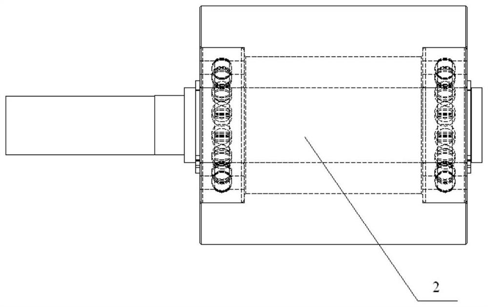
[0049] Depend on figure 1 , figure 2 and Figure 6 Given, different from Embodiment 1 and Embodiment 2, the upper cylinder fixing bracket 4 and the lower cylinder fixing bracket 14 are respectively provided with two sets of parallel screw holes 41 and 42 with different heights, and the screw holes 41 and 42 are all designed as a straight waist groove structure, the center line of the straight waist groove is perpendicular to the film 1, and the upper and lower ends of the straight waist groove are sealed with a semicircular arc tangent to the edge of the groove. The width of the straight waist groove is the same as the diameter of the semicircle, the distance between the centers of the upper and lower half arcs of each waist groove is 50mm, and the width of the waist groove is 11mm. Adjust the installation height of the cylinder according to the clamping force of the nip roller to achieve the desired clamping force and ensure that the clamping force of the film does not loo...


PUM

PropertyMeasurementUnit
lengthaaaaaaaaaa
widthaaaaaaaaaa

Abstract

The invention discloses a film processing device. The film processing device comprises a transverse pulling box and a transverse pulling unit, the transverse pulling unit comprises a transverse pulling pinch roll unit and a transverse pulling cutter unit which are arranged in the transverse pulling box, and the transverse pulling box comprises an N3 area, a first cooling area and a second cooling area which are sequentially arranged in the transverse pulling box in the traction direction of a film. The transverse pulling pinch roll unit comprises at least two sets of pinch roll groups. The at least two sets of pinch roll groups are separately arranged in the first cooling area and the second cooling area. Each set of pinch roller group is used for clamping the two sides of the film in the width direction. The transverse pulling cutter unit and the transverse pulling pinch roll unit are sequentially arranged in the traction direction of the film, and the transverse pulling cutter unit is arranged in the N3 area and used for cutting the edge of the film. The invention further discloses a film processing method, the film can be separated from the clamping of a chain clamp before entering the cooling areas, the longitudinal thermal shrinkage rate is improved, and the problem that the film is wrapped due to the fact that the film is beaten towards the middle under the action of no transverse tension is solved.

Description

technical field [0001] The invention relates to a film pulling device, in particular to a film processing device and a processing method. Background technique [0002] The main function of the transverse drawing machine (TDO) is to heat and stretch the film sheet transversely, so that the film thickness is uniform and the mechanical properties are stable. The horizontal stretching machine has two special chains that rotate endlessly. There are clamps on the chains, which can tightly clamp the two edges of the sheet and support them on the guide rails with variable width. With the help of the same direction of the two chain clamps, run synchronously. The sheet is firstly preheated in a slightly increased preheating section, then transversely stretched in a stretching zone with a larger expansion angle, and then heat treated in a parallel and shrinking heat treatment zone to shape and relax the film. Finally, cooling is carried out in parallel cooling zones to complete the t...

Claims


Application Information

Patent Timeline
Patent Type & Authority Applications(China)
IPC IPC(8): B29C55/12B29C35/16
CPCB29C55/12B29C35/16
Inventor 张坤李辉张磊磊姚从琪
Owner HEFEI LUCKY SCI & TECH IND
Why Eureka
Try Eureka