
Water treatment equipment and water treatment system

A technology for water treatment equipment and water outlet area, which is applied in multi-stage water treatment, water treatment parameter control, biological water/sewage treatment, etc., and can solve problems such as large occupied area.

Active Publication Date: 2021-10-08
浙江沃乐环境科技有限公司
View PDF5 Cites 0 Cited by
  • Summary
  • Abstract
  • Description
  • Claims
  • Application Information

AI Technical Summary

Problems solved by technology

[0004] Therefore, the technical problem to be solved by the present invention is to overcome the defects of laying flat and occupying a large area of ​​different treatment modules in the water treatment equipment in the prior art

Method used


Image

  • Water treatment equipment and water treatment system
  • Water treatment equipment and water treatment system
  • Water treatment equipment and water treatment system

Examples


Embodiment 1

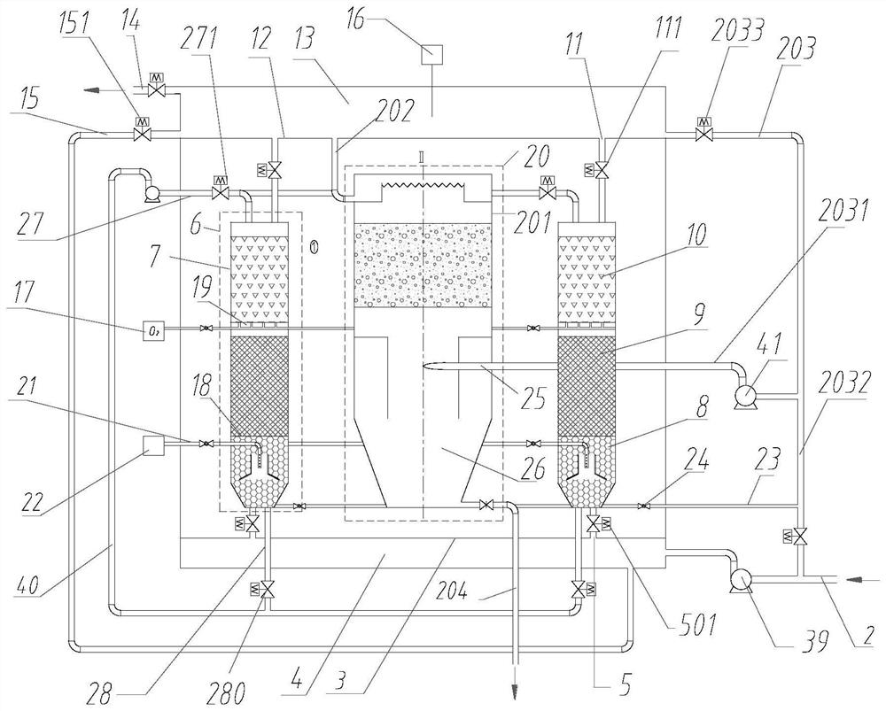
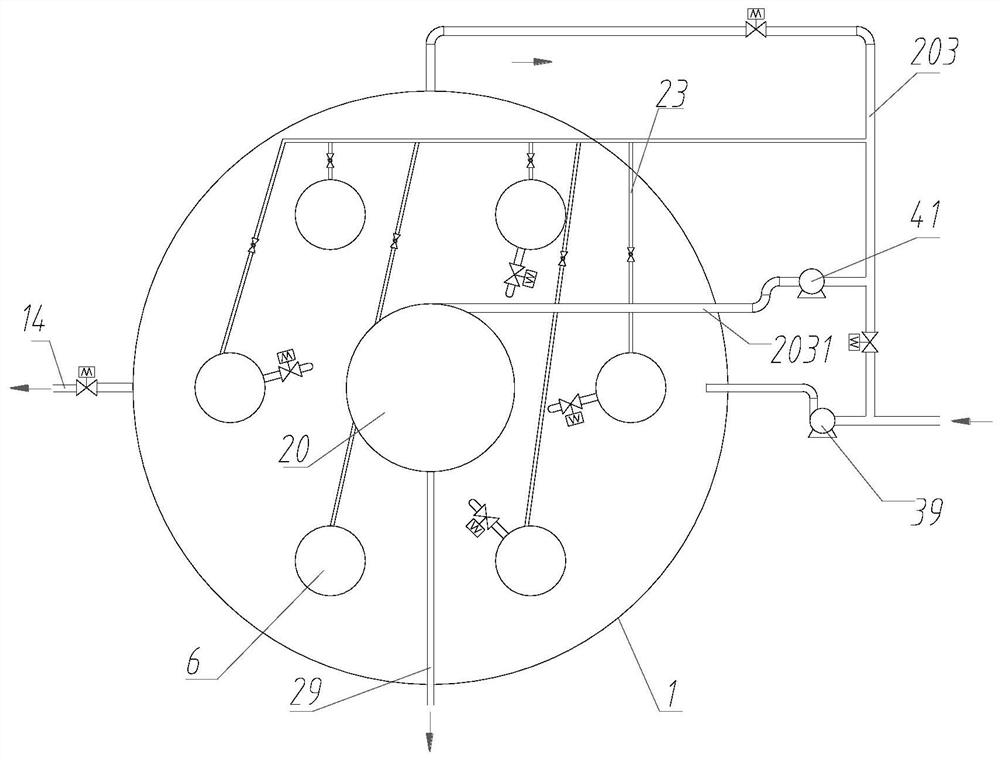
[0039] This embodiment provides a kind of water treatment equipment, such as figure 1 with figure 2 shown, including:

[0040] The housing 1 is provided with an accommodating chamber inside;

[0041] Specifically, the casing 1 itself is configured in a cylindrical shape, and an accommodating cavity is arranged inside. From the material point of view, the housing 1 itself is made of metal materials such as stainless steel.

[0042] The main water inlet pipe 2 is connected with the housing 1;

[0043] Specifically, the main water inlet pipe 2 itself is connected to the sewage source, and the external sewage can be introduced into the interior of the entire water treatment equipment through the main water inlet pipe 2 for purification operation. Simultaneously, in order to improve the water inlet water pressure, a water inlet pump 39 is provided on the water inlet main pipe 2 .

[0044] The first partition 3 is arranged in the accommodating chamber, and a water inlet area 4...

Embodiment 2

[0099] The present embodiment provides a water treatment system, comprising:

[0100] sewage source;

[0101] Specifically, there is no limitation on the source of the sewage source, which may be a sewage tank or a sewage pipe, as long as it is a structure that can realize the sewage injection operation.

[0102] In the water treatment equipment provided in embodiment 1, the water inlet main pipe is arranged downstream of the sewage source;

[0103] The sewage flowing in through the sewage source is treated and purified in the water treatment equipment. In this embodiment, for the sewage with relatively low carbon and nitrogen, the water treatment equipment can realize various functions such as biological nitrification, denitrification phosphorus removal, SS interception, etc. , can complete simultaneous denitrification, dephosphorization and SS removal. In addition, the small footprint of the water treatment equipment itself can make the footprint of the entire water treatm...


PUM


Abstract

The invention provides water treatment equipment and a water treatment system. The water treatment equipment comprises at least one filler unit which is arranged in a containing cavity and communicated with a filler unit water inlet pipe, wherein each filler unit comprises a filler shell, a first filler layer, a second filler layer and a third filler layer are sequentially arranged in each filler shell in the flowing direction of water flow, an anoxic environment is formed in the first filler layer, a micro-aerobic environment is formed in the second filler layer, and an oxygen-enriched environment is formed in the third filler layer; and the anoxic environment, the micro-aerobic environment and the oxygen-enriched environment can be integrated into one filler unit, so that the space occupied by the whole equipment is effectively reduced. Meanwhile, in the anoxic environment, the denitrification effect can be realized, so that the nitrogen element in the sewage can be removed. In the oxygen-enriched environment, phosphorus can be continuously absorbed under an aerobic condition according to the metabolism habit of phosphorus-accumulating bacteria, so that the dephosphorization operation on sewage is realized.

Description

technical field [0001] The invention relates to the technical field of environmental protection equipment, in particular to water treatment equipment and a water treatment system. Background technique [0002] With the continuous improvement of people's living standards, the amount of daily domestic sewage and industrial wastewater is also increasing. At present, there are mainly substances such as nitrogen, phosphorus, and suspended solids (SS) in sewage. Once these substances are discharged into the environment with sewage, they will cause great hidden dangers to human health and the surrounding environment. [0003] In the water treatment equipment in the prior art, in order to realize the removal of pollutants, different units such as coagulation area and sedimentation area are usually set up. At the same time, in order to realize the removal operation of different pollutants, multiple Groups of modules connected in series with each other. These modules are usually lai...

Claims


Application Information

Patent Timeline
IPC IPC(8): C02F3/30
CPCC02F3/301C02F3/308C02F2203/006C02F2301/046C02F2301/08C02F2303/14C02F2209/10C02F2209/14C02F2209/16
Inventor 陆慧锋阮贇杰俞言文刘芳王毅超马林
Owner 浙江沃乐环境科技有限公司
Learn More