Airflow suspension movement assembly for high-speed turbine dental handpiece and dental handpiece

A technology for dental handpieces and turbine components, used in dentistry, dental drilling, medical science, etc., can solve the problems of low power loss, low calorific value, and high rotational speed, and achieve low power loss, low calorific value, and high rotational speed. Effect

Pending Publication Date: 2021-10-12
佛山市耐可士医疗器械有限公司
View PDF0 Cites 2 Cited by
  • Summary
  • Abstract
  • Description
  • Claims
  • Application Information

AI Technical Summary

Problems solved by technology

[0004] In order to overcome the above-mentioned deficiencies in the prior art, one of the tasks of the present invention is to provide a kind of airflow suspension core assembly for the high-speed turbine dental handpiece, which forms a sleeve-shaped air film in the radial direction of the rotating shaft by compressed air during work, and The upper and lower ends of the impeller form a flat cushion-like air film to support the radial and axial support of the turbine assembly, so that the turbine assembly can be suspended in both the radial and axial directions without direct contact with the sleeve. When rotating at high speed, the friction force is very small, the power loss is small, the speed is high, the noise is low, the calorific value is low, it is not easy to wear, the service life is long, and it does not need lubricating substances, and there will be no problems caused by the overflow of lubricating substances, and it is easier Manufacture and assembly; the second task of the present invention is to provide a dental handpiece that adopts the above-mentioned air suspension core assembly

Method used


Image

  • Airflow suspension movement assembly for high-speed turbine dental handpiece and dental handpiece
  • Airflow suspension movement assembly for high-speed turbine dental handpiece and dental handpiece
  • Airflow suspension movement assembly for high-speed turbine dental handpiece and dental handpiece

Examples


Embodiment 1

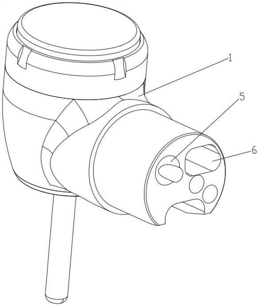
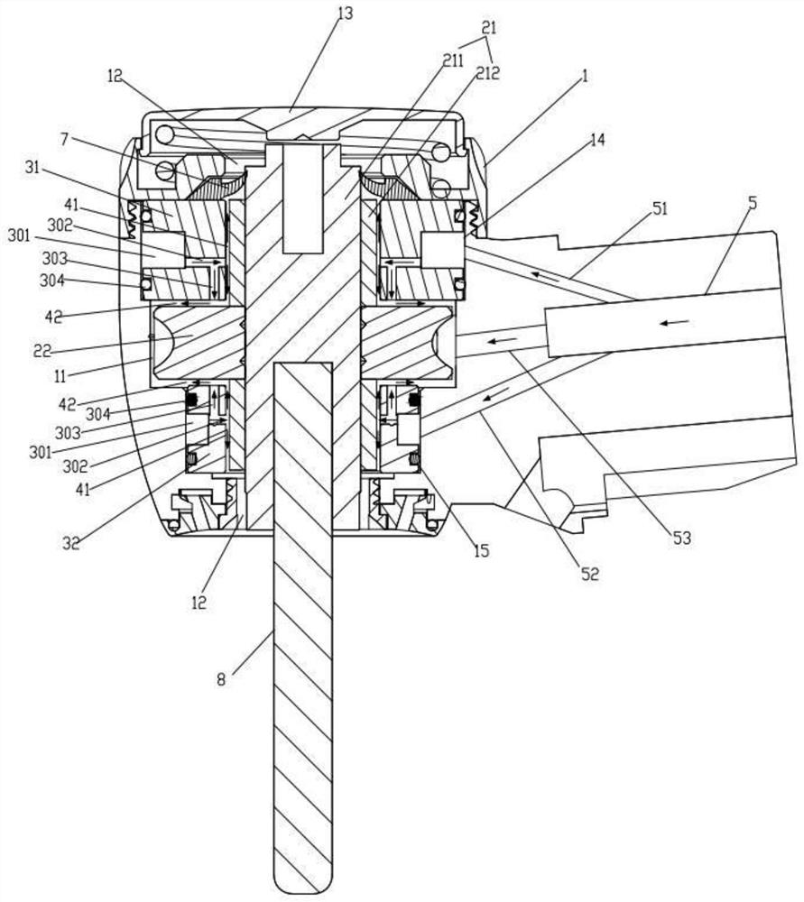
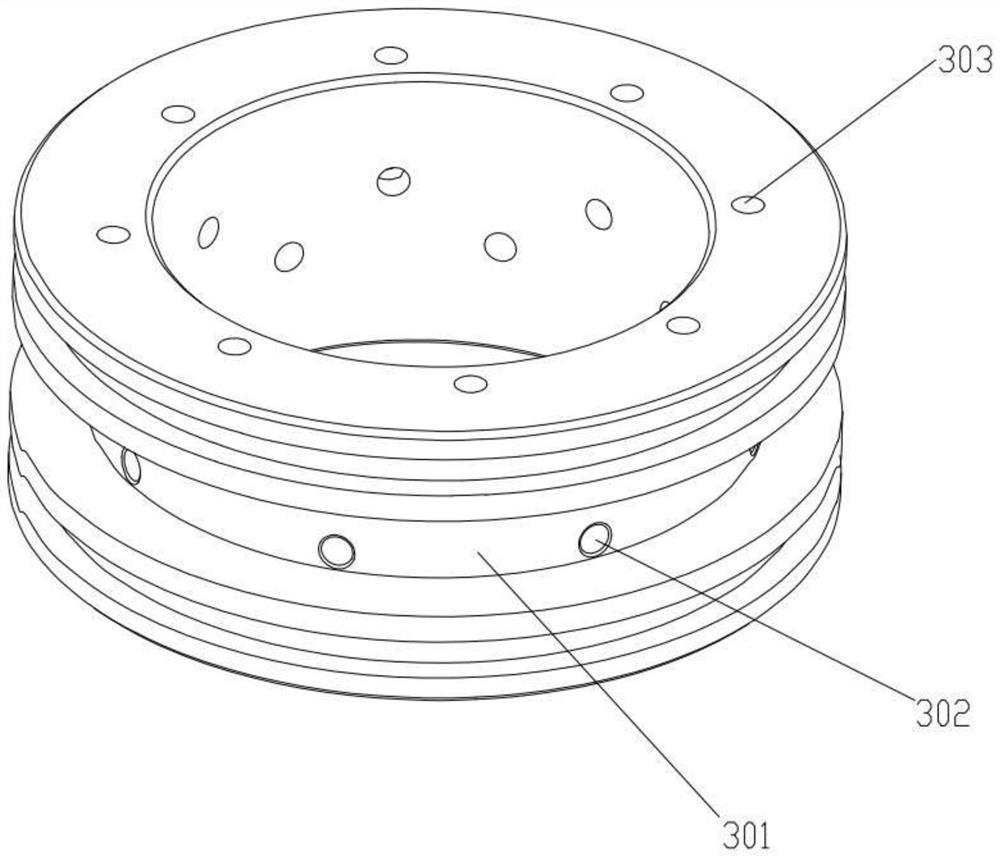
[0026] Such as Figure 1-3As shown, the air-suspension core assembly for high-speed turbine dental handpieces includes a handpiece housing 1, a turbine assembly rotatably arranged in the handpiece housing 1, and a bearing for supporting the turbine assembly. The turbine assembly includes a rotating shaft 21 and the turbine 22 fixedly sleeved outside the rotating shaft 21, the turbine 22 is placed in the turbine cavity 11 in the head housing 1, the rotating shaft 21 includes a shaft 211 and two steel sleeves fixedly sleeved outside the shaft 211 A barrel 212, the lower end of the shaft is used to connect the bur 8, two sleeves 212 are arranged at intervals along the axial direction and are respectively located at the upper and lower ends of the turbine 22, and the bearings include axial intervals arranged at the upper and lower ends of the turbine 22. The upper bushing 31 and the lower bushing 32 at both ends, the upper bushing 31 and the lower bushing 32 are all fixed in the m...

Embodiment 2

[0032] Such as Figure 4 As shown, a dental handpiece 100 includes a handle 20 and a handpiece 10 installed at one end of the handle 20 , the handpiece includes the air suspension core assembly in Embodiment 1. Since the performance, service life, manufacturing cost and efficiency of the dental handpiece depend to a large extent on the movement assembly, and the bearing plays a key role in the movement assembly, the dental handpiece of the present invention, due to the above-mentioned airflow suspension Movement components, so its overall performance is better, the power loss is small, the speed is high, and the noise is low, the heat is low, it is not easy to wear, the life is longer, and the manufacturing cost is lower, and the manufacturing efficiency is higher.


PUM


Abstract

The invention relates to the technical field of medical instruments, in particular to an airflow suspension movement assembly and a dental handpiece, the airflow suspension movement assembly comprises a handpiece shell, a turbine assembly and a bearing, the bearing comprises an upper shaft sleeve and a lower shaft sleeve which are arranged outside a rotating shaft in a sleeving mode, a first gap is formed between the upper shaft sleeve and the rotating shaft, the upper shaft sleeve and the lower shaft sleeve are parallel to the upper end face and the lower end face of a turbine respectively to form a second gap, the upper shaft sleeve and the lower shaft sleeve are each provided with an annular air groove and a plurality of first throttling holes and second throttling holes, one ends of the first throttling holes and the second throttling holes are communicated with the annular air grooves, and the other ends of the first throttling holes and the second throttling holes are communicated with the first gap and the second gap respectively. When the turbine assembly works, a sleeve-shaped air film is formed in the radial direction of the rotating shaft through compressed air, flat gasket-shaped air films are formed on the upper end face and the lower end face of an impeller, and therefore the turbine assembly can be in a suspension state in the radial direction and the axial direction, and the turbine assembly is small in friction force, low in noise, and low in heat productivity when rotating at a high speed, not prone to abrasion, long in service life and easier to machine, manufacture and assemble.

Description

technical field [0001] The invention relates to the technical field of medical devices, in particular to an air suspension core component and a dental handpiece used for a high-speed turbine dental handpiece. Background technique [0002] High-speed turbine dental handpiece is a commonly used medical device in the department of stomatology. Its working principle is to use compressed air to blow the turbine to rotate at high speed, and then drive the rotating shaft and the needle to rotate at high speed. The speed is usually above 200,000 rpm to cut teeth It can be used to remove carious tissues from the body, or prepare porcelain teeth, and can also be used to polish dentures, etc. There are many varieties of high-speed turbo dental handpieces. In addition to the differences in quality, there are also various appearances and various additional functions. For example, there are thimble type, screw type and Button type; cooling methods include single-hole spray, double-hole s...

Claims


Application Information

Patent Timeline
Patent Type & Authority Applications(China)
IPC IPC(8): A61C1/05
CPCA61C1/05A61C1/052
Inventor 李强
Owner 佛山市耐可士医疗器械有限公司
Why Eureka
Try Eureka